32
33
Assembly and Parts, Cont.
Bypass Valve Assembly
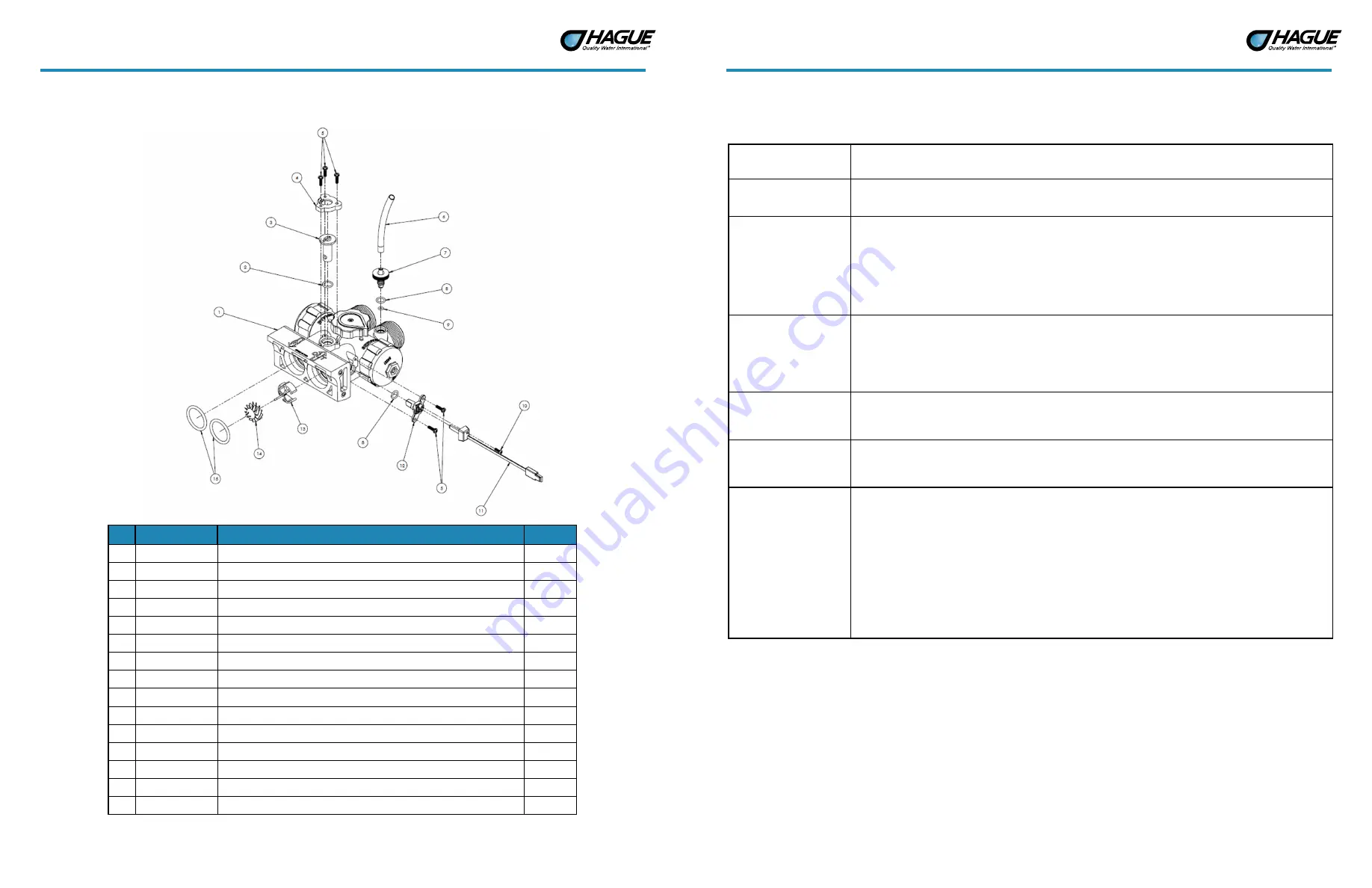
Figure 14: Bypass Valve Assembly
Current Part #
Description
Quantity
1
100241175
Bypass Valve Assembly (also includes items 2-15)
1
2
100241868
O-Ring
1
3
100241804
Blending Dial
1
4
100241811
Cap - Blending Dial
1
5
100238196
Screw
5
6
100241863
Tubing 4.0-inch
1
7
100241805
Test Port Valve
1
8
100241869
O-Ring
2
9
100241820
O-Ring
1
10
100241861
Screw
1
11
100238200
Turbine Sensor Wire with Cap
1
12
100241189
Turbine Sensor Housing
1
13
100238202
Plastic Turbine Axle
1
14
100238201
Turbine Assembly
1
15
100242050
O-Ring
2
Assembly and Parts, Cont.
Bypass Valve Assembly Cont.
100241811
Blending Dial Cap
The Cap should be held in place by the three 1/2-inch self-tapping screws and be in the proper
orientation.
100241804
Blending Dial
The Dial permits the addition of “untreated water” into the soft water outlet. It is closed when pointing
toward the Main Control Valve and open when pointing toward the inlet side.
100241805
Test Port Valve
The Test Port Valve is used to draw water samples from the unit. When the Bypass Valve is in the Service
position, the water tested should be soft, treated water. When the Bypass Valve is in Bypass position, the
water treated is from the raw, incoming water supply.
Note:
There are two types of seals on the Test Port. One seal is an O-Ring which seals off the threaded
area when the Valve is opened. The other seal is a compression O-Ring seal between the Test Port Valve
material and the Bypass Housing. If this seal is “overtightened,” it can damage the O Ring and cause a
permanent leak.
100238200
Turbine Sensor Wire
with Cap
Picks up the magnetic field from the Turbine and relays it to the Controller. Care should be taken when
putting the Sensor Wire into the Sensor Housing. The cap is then put in place and the self tapping mount-
ing screw is installed. A slot is provided in the cap for the wire to exit. The three wire socket connector
must be properly installed in the controller. Stops on the connector prevent improper (upside down)
assembly. Do not force the connector past the stops.
100238202
Plastic Turbine Axle
Sits on a ridge in the Main Control Valve side of the outlet stream of the Bypass Valve Assembly. Needs
to fit around the Turbine Sensor Housing (100241189) when assembled. If the Plastic Turbine Axle is not
correctly seated, the Sensor Wire may not sense the Turbine magnet.
100238201
Turbine Assembly
The Turbine must have a 1/8-inch diameter Rare Earth magnet pressed into place adjacent to the axle
opening. When assembled to the axle, the Turbine should spin freely. Do not use any lubricants. If the
Turbine should become “jammed,” clean and flush the Turbine and Bypass Valve.
100241175
Bypass Valve Assembly
Makes the connection between the plumbing and the appliance. The Bypass Valve Assembly allows wa-
ter to bypass the appliance for service or when untreated water is desired. The recommended seal for the
1-1/4-inch male inlet-outlet threads is the plastic Bypass Nut (100241810), O-Ring (100241873), and 1
inch CPVC CTS Adapter (100241817). Make sure the O-Ring is between the Bypass Valve Assembly and
the flange on the CPVC Adapter. The O Ring seal areas at the Main Control Valve inlet and outlet must be
smooth, free of defects and debris, and lubricated with silicone grease before assembling. When attach-
ing to the Main Control Valve, put the O-Rings on the male bosses on the Main Control Valve and push
the Bypass Valve Assembly into place; if not, the O-Rings may be “pinched.” If the O Rings get pinched,
replace with new ones. The Bypass Valve Assembly is pre-assembled and is not considered field-service
-
able. If the Bypass Valve Assembly is damaged it must be replaced with a new assembly.


