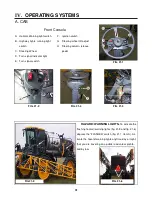
IV.
OPERATING SYSTEMS
30
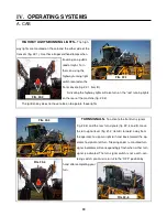
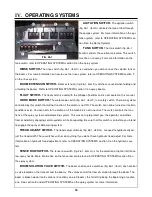
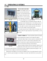
FIELD LIGHTS AND WORK
LIGHTS–
The field lights (fig. 30-2), lo-
cated on the front of the cab with the
headlights, are activated by pushing the
switch located on the upper right cab
headliner (fig. 30-1, item A). Use these
lights when operating in the field after
dark. Turn them off before entering a public roadway.
The work lights (fig. 30-3), located on each boom cradle, one
facing forward and one facing backward, are activated by pressing the
second switch (fig. 30.1, item B) located on the right upper cab head-
liner. These lights can also be used when operating in the field after
dark. Turn them off before entering a public roadway.
The ignition key has to be on to operate these sets of lights, but ex-
tended use without the engine operating to charge the battery is not rec-
ommended.
FIG. 30-1
A
B
FIG. 30-2
FIG. 30-3
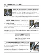
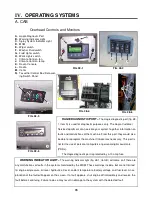
CLIMATE CONTROLS -
The climate controls (fig. 30-4) are continu-
ous adjusting dial switches located on the front upper cab headliner.
Adjusting Fan Blower Speed– fan blower speed is controlled by the left
rotary dial (fig. 30-4, item A). To increase the fan speed, rotate the dial
clockwise. To reduce the fan speed, rotate the dial counterclockwise. To
shut the fan off, rotate the dial all the way counterclockwise.
Adjusting Temperature Setting– forced air temperature adjustments are
controlled by the right rotary dial (fig. 30-4, item B). Temperature control is
a continuously variable adjustment. To increase the forced air temperature, rotate the dial clockwise. To de-
crease the forced air temperature, rotate the dial counterclockwise.
Operating the Air Conditioning– to activate the air conditioner, press the air conditioning switch (fig. 30-4,
item C). Adjust fan speed and temperature accordingly. See section B under SERVICE for servicing informa-
tion.
A. CAB
FIG. 30-4
A
B
C
Содержание UpFront STS 14 Combo
Страница 14: ...9 650848 On ladder pivot tube 2 on each cutter head housing 650819 Quad puller head 650820 I SAFETY DECALS...
Страница 148: ...151 IX TROUBLE SHOOTING TASSELTROL WIRE DIAGRAM FIG 151 1 2 1 TROUBLE SHOOTING...
Страница 149: ...152 IX TROUBLE SHOOTING NOTES...
Страница 157: ...NOTES...

