IV.
OPERATING SYSTEMS
26
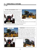
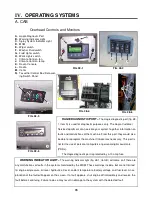
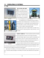
AGITATION SWITCH-
The agitation switch
(fig. 26-1, item A) controls the rate of flow through
the sparge system. For more information on the agi-
tation system, refer to OPERATING SYSTEMS sec-
tion D on the Spray Systems.
TANK SWITCH-
The tank switch (fig. 26-1,
item B) controls the solution tank valve. This switch
must be on to spray. For more information on the
tank switch, refer to OPERATING SYSTEMS section D on the spray system.
RINSE SWITCH-
The rinse switch (fig. 26-1, item C) is used when you wish to rinse the solution tank or
the booms. For more information on how to use the rinse system, refer to OPERATING SYSTEMS section F
on the rinse system.
BOOM EXTENSION SWITCH-
Boom extension (fig. 26-1, item D) switches are used when folding and
unfolding the booms. Refer to OPERATING SYSTEMS section C on spray booms.
FLOAT SWITCH-
The float switch is used with the Nitrogen Tool Bar and is not covered in this manual.
WORK MODE SWITCH-
The work mode switch (fig. 26-1, item F) is a safety switch. There are systems
controlled by this switch that will not function if the switch is not ON. The switch can not be turned on if certain
conditions exist. You can not turn the switch on if the machine is not in neutral. The switch controls the func-
tions of the spray system and detasseling system. This was set up to protect you, the operator, and others
from accidentally engaging certain systems while transporting. Be sure that this switch is on before you intend
to engage the spray or detasseling system.
TREAD ADJUST SWITCH-
The tread adjust switches (fig. 26-1, item G) are used to hydraulically ad-
just the tread width. These switches will not do anything if you do not have hydraulic tread adjust. For more
information on hydraulic tread adjustment, refer to OPERATING SYSTEMS section C on the hydraulic sys-
tem.
FENCE ROW SWITCH-
The fence row switch (fig. 26-1, item H) is for the selection of right or left fence
row spray nozzle. More information on the fence row can be found in OPERATING SYSTEMS section D on
the spray system.
BOOM SOLUTION VALVE SWITCH-
The boom solution valve switches (fig. 26-1, item I) each control
a valve located on the transom and the booms. The valves control the flow of solution through the boom. The
boom is broken down into 5 sections (3 sections on a 60’ boom), the far left tip being the beginning of section
one. See section E under OPERATING SYSTEMS on the spray system for more information.
A
B
C
D
E
F
G
H
I
FIG. 26-1
Содержание UpFront STS 14 Combo
Страница 14: ...9 650848 On ladder pivot tube 2 on each cutter head housing 650819 Quad puller head 650820 I SAFETY DECALS...
Страница 148: ...151 IX TROUBLE SHOOTING TASSELTROL WIRE DIAGRAM FIG 151 1 2 1 TROUBLE SHOOTING...
Страница 149: ...152 IX TROUBLE SHOOTING NOTES...
Страница 157: ...NOTES...


