IV.
OPERATING SYSTEMS
43
C. HYDRAULIC SYSTEM
SPRAY BOOMS–
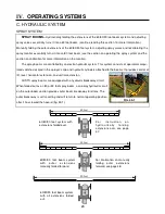
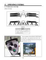
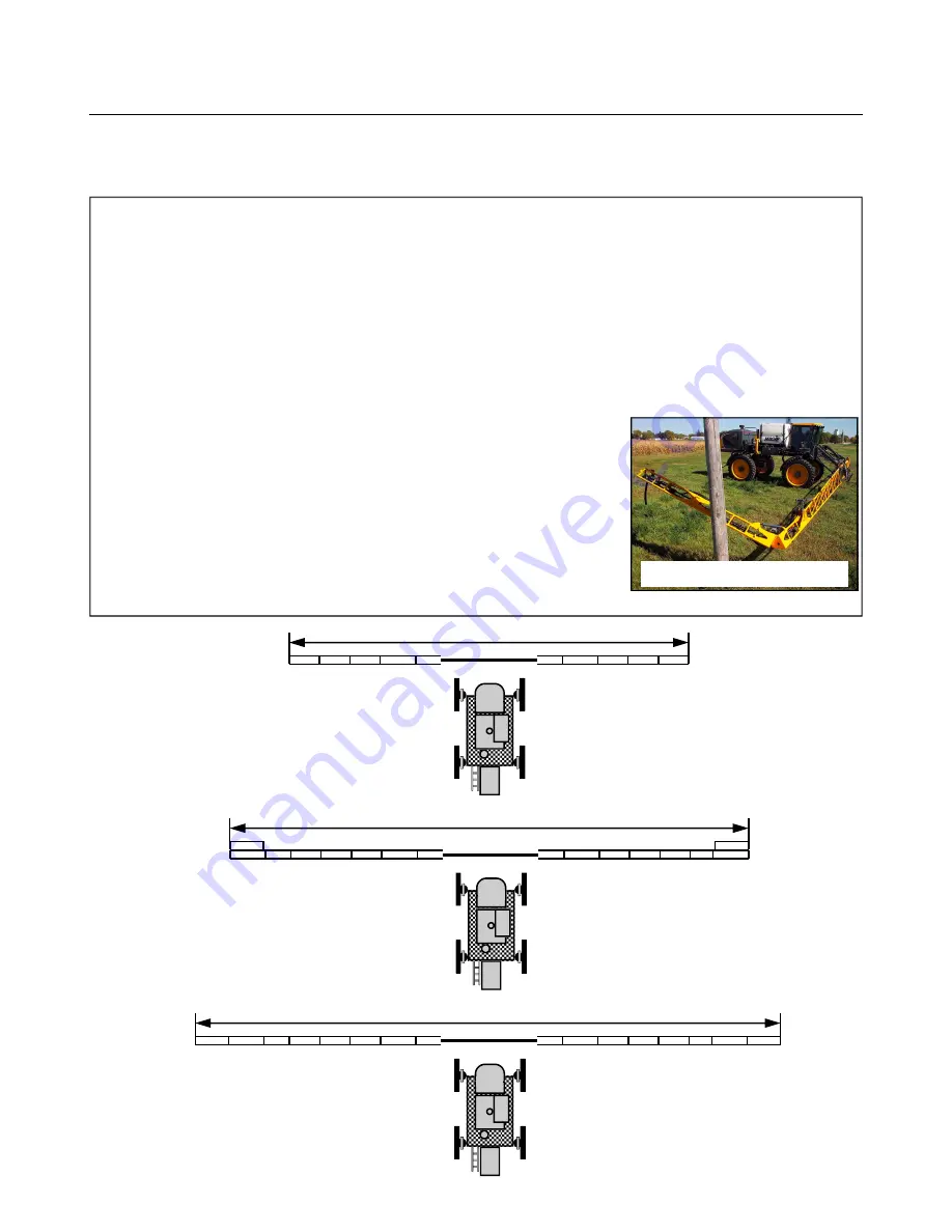
Hydraulically folding the extensions of the 60/80/90 foot boom system and adjusting
spray valves essentially turns it into a 60 foot boom. (continue reading this section for more information).
Manually folding the outer extensions of the 60/80/90 foot system, adjusting spray valves and recalibrating the
spray monitor essentially turns it into an 80 foot boom (see the section on operating the spray system and the
section on calibration for more information on the monitor).
The spray booms are controlled by an electro-hydraulic system. This system consists of operator manipu-
lated switches located in the sprayer’s cab and hydraulic cylinders attached to the booms. It provides control of
lift, level, horizontal extension, and vertical extension.
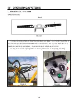
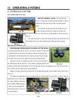
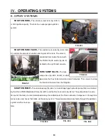
All STS spray booms are equipped with a hydraulic breakaway circuit.
When folded out as an 80 or 90 foot spray boom, a one-way hydraulic circuit
on the outer boom section provides outer boom breakaway functions. The
outer breakaway is self-resetting and will return to normal operating position
after it has cleared the hazard (fig. 43-1).
FIG. 43-1
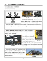
60/80/90 foot boom system
with all extensions folded
out.
90 feet
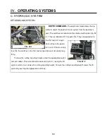
60/80/90 foot system with
extensions folded over.
60 feet
F o r
i n s t r u c t i o n
o n
h y d r a u l i c a l l y
f o l d i n g
extensions over, see page
47.
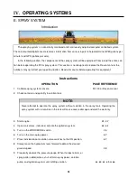
60/80/90 foot boom system
wit h
out er
ex t ens ions
manually folded forward.
80 feet
For information on manually
folding
outer
extensions
forward, see page 48.
SPRAY SYSTEM
Содержание UpFront STS 14 Combo
Страница 14: ...9 650848 On ladder pivot tube 2 on each cutter head housing 650819 Quad puller head 650820 I SAFETY DECALS...
Страница 148: ...151 IX TROUBLE SHOOTING TASSELTROL WIRE DIAGRAM FIG 151 1 2 1 TROUBLE SHOOTING...
Страница 149: ...152 IX TROUBLE SHOOTING NOTES...
Страница 157: ...NOTES...


