


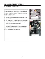
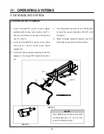
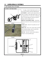


1. Install Tasseltrol
®
/LS sensor mount support
weldment with the two nylon washers (fig 77-1,
item B) in the forward- most hole of the tool bar
(fig. 77-1, item A).
2. Install the Tasseltrol
®
/LS sensor mount weld-
ment (fig. 77-1, item C) to the sensor mount
support arm.
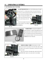
3. Install the cable assembly according to the wire
diagram in the Hagie STS Combo Parts Man-
ual.
4. Turn the ignition key switch to the “ON” position
to check the sensor installation. DO NOT start
the engine.
5. Attach the depth command actuator (fig. 77-2)
to the light sensor mount and the tool bar.
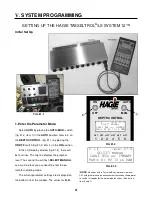
LS SYSTEM AND DEPTH COMMAND-
NOTE:
Over tightening of the sensor arm pivot
mounting bolt (fig. 77-1, item A) may
cause the actuator to stall.
FIG 77-2
77
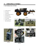
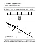
IV.
OPERATING SYSTEMS
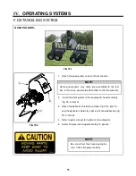
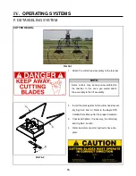
F. DETASSELING SYSTEM
FIG 77-1
Tool Bar
B
C
A
Содержание UpFront STS 14 Combo
Страница 14: ...9 650848 On ladder pivot tube 2 on each cutter head housing 650819 Quad puller head 650820 I SAFETY DECALS...
Страница 148: ...151 IX TROUBLE SHOOTING TASSELTROL WIRE DIAGRAM FIG 151 1 2 1 TROUBLE SHOOTING...
Страница 149: ...152 IX TROUBLE SHOOTING NOTES...
Страница 157: ...NOTES...