background image

Manager:

Planner T

hic
knesser

C

CUTTING, ST

ABBING,

LOW

CRUSHING

Authorised and signed by:

Developed in Co-operation Between 

A.W

.I.S.A

 and 

Australia Chamber of Manufactures

This program is based upon the Safe W

ork 
Australia, Code of Practice  -  Managing Risks of Plant in the W

orkplace  ( WHSA

 201

1 No10 )

NEW

 MACHINERY 

HAZARD IDENTIFICATION, 

ASSESSMENT & CONTROL

Keep hands clear of all blades and moving parts. Use a push stick where necessary

.

O

D

SHEARING

Safety of

ficer:

Ensure to use correct feed rates for material.

W

ear hearing protection as required.

MEDIUM

PLANT SAFETY

 PROGRAM

No.

Hazard

Identification

Item

Hazard

Assessment

H

B

ENT

ANGLEMENT

MEDIUM

A

HIGH

Risk Control Strategies

(Recommended for Purchase / Buyer / User)

Heavier timber must be supported

Eliminate, avoid loose clothing / Long hair etc.

Isolate power to machine prior to any checks or maintenance.

Be sure that when rising and falling planner tables hands are well away from locating, clamping 

and pivoting area.

Care must be taken when handling knives.

Must be connected to dust extraction

OTHER HAZARDS, NOISE,

MEDIUM

Make sure all guards are secured shut when machine is on.

A

 face mask must be worn at all times.

PUNCTURING

Do not open or clean inside until the machine has completely stopped.

Plant Safety Program to be read in conjunction with manufactures instructions

LOW

STRIKING

MEDIUM

Do not stand behind timber when feeding into machine.

Make sure all guards are secured shut when machine is on.

All electrical enclosures should only be opened with a tool that is not to be kept with the machine.

Machine should be installed & checked by a Licensed Electrician.

Revised Date:

www

.machineryhouse.com.au

www

.machineryhouse.co.nz

12th March 2012

DUST

.

ELECTRICAL

Page 30

Instructions Manual for T-13A (W813)

1

1/9/19

Содержание T-13A

Страница 1: ...INSTRUCTION MANUAL T 13A Thicknesser Bench Mount 240V 330 x 152mm W813 Page 1 Instructions Manual for T 13A W813 11 09 2019 ...

Страница 2: ...13 PLANER User Manual Read and understand this manual before using machine T 13A Model Number www machineryhouse com au www machineryhouse co nz Page 2 Instructions Manual for T 13A W813 11 09 2019 ...

Страница 3: ...r machine at time of print However changes may be made to your machine or this manual at any time with no obligation to HAFCO Woodmaster INTRODUCTION SECTION 1 SECTION 2 SECTION 3 SECTION 4 Definition of Terms SECTION 5 Feature Identification SECTION 6 General Safety SECTION 7 Product Safety SECTION 8 Electrical Requirements SECTION 9 SECTION 10 SECTION 11 SECTION 12 SECTION 13 SECTION 14 Troubles...

Страница 4: ...m Width 508 mm Depth 622 mm Total Net Weight 25 kg Shipping Dimensions Height 508 mm Width 558 mm Depth 406 mm Gross Weight 27 kg DEFINITION OF TERMS Cutterhead A rotating piece of adjustable blades that removes material from the workpiece Gum Pitch or Resin A sticky sap based residue that comes from wood products Leading End The end of the workpiece that is pushed into the planer first Snipe Goug...

Страница 5: ...ION A Infeed Table B Thickness Scale C D Power Switch E Raise Lower Handle Depth of Cut Indicator F Dust Port A B E D F C www machineryhouse com au www machineryhouse co nz Page 5 Instructions Manual for T 13A W813 11 9 19 ...

Страница 6: ... the user to useful informa tion about proper operation of the machine GENERAL SAFETY DANGER NOTICE CAUTION Exposure to the dust created by power sanding saw ing grinding drilling and other construction activities may cause serious and permanent respiratory or other injury including silicosis a serious lung dis ease cancer and death Avoid breathing the dust and avoid prolonged contact with dust 2 ...

Страница 7: ...at they operate properly are not damaged and perform their intended functions Check for alignment binding or breakage of all moving parts Any guard or other part that is dam aged should be immediately repaired or replaced 16 Ground all machines If any machine is supplied with a 3 prong plug it must be plugged into a 3 contact electrical receptacle The third prong is used to ground the tool and pro...

Страница 8: ...eliminate the need for an extension cord 27 Wear proper clothing DO NOT wear loose clothing gloves neckties or jewellery These items can get caught in the machine during operations and pull the operator into the moving parts Users must wear a protective cover on their hair if the hair is long to prevent it from contacting any moving parts 28 SAVE these instructions and refer to them frequent ly an...

Страница 9: ...11 DO NOT pull the jointer by the power cord NEVER allow the power cord to come in contact with sharp edges hot surfaces oil or grease 12 DO NOT unplug the jointer by pulling on the power cord ALWAYS grasp the plug not the cord 13 REPLACE a damaged cord immediately DO NOT use a damaged cord or plug If the jointer is not operating properly or has been damaged left out doors or has been in contact w...

Страница 10: ...into a matching electrical receptacle that is properly installed and grounded in accordance with ALL local codes and ordinances If a plug is provided with your machine DO NOT modify the plug If it will not fit your electrical receptacle have a qualified electrician install the proper connections to meet all electrical codes local and state IMPROPER ELECTRICAL CONNECTION of the equip ment grounding...

Страница 11: ...xtension cord immediately or have it repaired by a qualified person before using it Protect your extension cords from sharp objects exces sive heat and damp or wet areas CAUTION Κ Electrocution or fire could result if this machine is not grounded properly or if the electrical configura tion does not comply with local and state electrical codes Κ MAKE CERTAIN the machine is disconnected from power ...

Страница 12: ...ctive coatings are removed completely UNPACKING INVENTORY After cleaning apply a good quality paste wax to any unpainted surfaces Make sure to buff out the wax before assembly Compare the items to inventory figures verify that all items are accounted for before discarding the shipping box If any parts are missing do not attempt to plug in the power cord and turn ON the machine The machine should o...

Страница 13: ... THAT THE MACHINE IS DISCON NECTED FROM THE POWER SOURCE WARNING 1 Attach the depth adjustment handle A to the shaft B and fasten in place with 1 Hex Soc Head screw Tighten screw using supplied hex wrench SEE FIG 1 Fig 1 Fig 2 ATTACHING DUST PORT The Dust Port is to be used when the planer to be connected to a dust collector It has a 4 port on it to accomodate most dust collection systems To insta...

Страница 14: ... the infeed table 4 Repeat this process for adjusting the outfeed table RAISING AND LOWERING HEAD ASSEMBLY The head assembly consists of the cutterhead and knives feed rollers cutterhead guard and the motor Raising and lowering of the head assembly controls the depth of cut on the planer To adjust 1 To raise the head assembly A turn the adjusting handle B clockwise SEE FIG 5 Fig 5 2 To lower the h...

Страница 15: ...he cutterhead with the supplied Hex wrench Rotate it to the position where the sharp edge of the blade is not visiable from your sight angle SEE FIG 7 Loosen the screw on both sides and remove the defector Use the elevating handle to low down the upper frame to 2 Fig 7 4 Use the supplied Hex wrench insert it into the side cover hole Rotate it to the lock position SEE FIG 8 Using the supplied hex w...

Страница 16: ... the knife This is normal as it allows for repositioning of the knives in case one of the knives gets a nick in it NOTE In order to rotate the cutterhead you will have to depress the red lever This will unlock the cutterhead allowing you to rotate it to the next knife to be changed THICKNESS SCALE ADJUSTMENT The thickness scale located on the right of the planer shows the thickness of the finished...

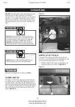
Страница 17: ...haling dangerous dust or airborne particles WARNING WARNING WARNING This planer is designed to process wood ONLY POWER SWITCH The planer is turned on by flipping the switch into the up position and it is turned off by flipping the switch in the down position This planer is also equipped with a special lockout toggle switch that prevents unauthorized use To prevent unauthorized use of the planer si...

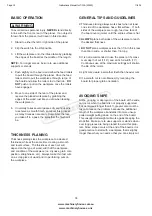
Страница 18: ...ng attempt Also before each use of the planer make it a habit of checking for loose fasten ers fittings or hardware Turn the planer ON and allow it to reach full speed Pay close attention to any exces sively loud noises that may be coming from the planer or any excessive vibration If either occurs shut down the planer immediately checking again for loose hard ware Go through the ASSEMBLY and ADJUS...

Страница 19: ...ss etc Always make thin test cuts on a scrap piece of wood prior to performing cuts on the workpiece WARNING GENERAL TIPS AND GUIDELINES Κ Thickness planing always works best when at least one side of the workpiece has a flat surface If both sides of the workpiece are rough feed one face of the board over a jointer until the entire surface is flat Κ ALWAYS plane both sides of the workpiece to reac...

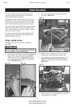
Страница 20: ... LUBRICATION The gears in the gear box should be lubricated periodically MAKE CERTAIN THAT THE MACHINE IS DISCON NECTED FROM THE POWER SOURCE WARNING Fig 14 2 Remove the side panel to expose the gear box cover B SEE FIG 16 3 Remove the two screws C in order to remove the gear box cover and access the gear box 4 Place a light coat of multi purpose grease on the teeth of the gears D and a light coat...

Страница 21: ...e spring C and the wire D SEE FIG 19 Fig 19 D C B 3 If the carbon of either brush is worn down to 3 16 or less both brushes should be replaced Also if the spring or wire are burned or damaged in any way both brushes should be replaced BLADE REPLACEMENT For information on replacing blades refer to the section labeled ADJUSTING REPLACING KNIVES in the ADJUSTMENT section of this manual ORGANIZING POW...

Страница 22: ... t u c l l u D Too deep a blade setting Reduce depth of cut e t a r d e e f r e w o l s e s U d e e p s g n i d e e f t c e r r o c n I Depth scale incorrectly set Adjust depth scale e c r u o s r e w o p k c e h C n i d e g g u l p t o N Blown circuit Replace fuse reset breaker or call electrician y e k t u o k c o l e c a l p e R d e v o m e r y e k t u o k c o L Unit overloaded Circuit overload...

Страница 23: ...NOTES 22 www machineryhouse com au www machineryhouse co nz Page 23 Instructions Manual for T 13A W813 11 9 19 ...

Страница 24: ...23 www machineryhouse com au www machineryhouse co nz PARTS Page 24 Instructions Manual for T 13A W813 11 9 19 ...

Страница 25: ...24 www machineryhouse com au www machineryhouse co nz Page 25 Instructions Manual for T 13A W813 11 9 19 ...

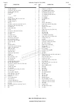
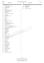
Страница 26: ...NION GEAR 1 80 M6xP1 0x12L HEX SOC HD CAP SCR 6 81 MOTOR MTG PLATE 1 82 CURSOR 1 83 M3xP0 5x20L RUND HD SCR 2 84 M5xP0 8x8L PAN HD SCR L WASH 2 85 EXT TOOTH WASHER 2 86 M4xP0 7x12L PAN HD SCR 3 87 SPECIAL NUT 1 88 POINTER HOUSING 1 89 COIL SPRING 1 90 ROD POINTER ELEVATING 1 91 POINTER 1 92 BUSHING 1 93 M4xP0 7x10L NYLOCK SCR PAN CR W WASH 1 94 POINTER HOUSING 1 95 INDICATOR DEPTH ASSY 1 96 MOTOR ...

Страница 27: ...8x8L SCR PAN HD CR TYTT 1 159 LOCKWASHER EXT 1 160 GROUND WIRE 1 161 MOTOR END CAP 1 162 WAVE WASHER 1 163 BALL BEARING 2 164 ARMATURE 1 165 SLEEVE 1 166 POWER CORD CLAMP 1 167 FIELD 1 168 M4 8x75L TAP SCR PAN HD L WASH 2 169 MOTOR HOUSING 1 170 M5xP0 8x8mm HEX SOC SET SCR 2 171 RING RETAINING 1 172 BRUSH HOLDER 2 173 BRUSH 2 174 BRUSH CAP 2 175 INSULATOR 1 175 1 SWITCH FIXED PLATE 1 176 SWITCH CO...

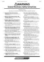
Страница 28: ...re connecting 14 Use correct amperage extension cords Undersized extension cords overheat and lose power Replace extension cords if they become damaged 15 Keep machine well maintained Keep blades sharp and clean for best and safest performance Follow instructions when lubricating and changing accessories 16 Keep machine well guarded Make sure guards on machine are in place and are all working corr...

Страница 29: ...way from the infeed roller during operation to prevent serious injury 13 Never look inside thicknesser Wood chips fly around inside the thicknesser at a high rate of speed Do not look inside the thicknesser remove guards or covers during operation 14 Operating position The workpiece may kick out during operation To avoid getting hit stand to the side of the machine during the entire operation 15 U...

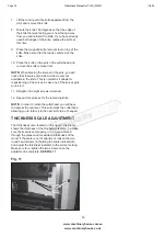
Страница 30: ...ir etc Isolate power to machine prior to any checks or maintenance Be sure that when rising and falling planner tables hands are well away from locating clamping and pivoting area Care must be taken when handling knives Must be connected to dust extraction OTHER HAZARDS NOISE MEDIUM Make sure all guards are secured shut when machine is on A face mask must be worn at all times PUNCTURING Do not ope...

Отзывы: