background image


12 


5.52.290.00.01.08 


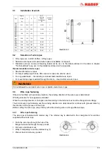
By pulling the wire rope, the retainer key gets 
stuck into the pocket and locks the wire rope 
safely.  

It may be necessary to insert the retainer key a 
little bit into the hub with a soft tool before the wire 
rope can be loaded. 


Illustration 5


According to the winding direction there will be 2 
rope direction angles how you can haul off the 
rope from the drum. 
See chapter “design”. 


Illustration 6


6.4 

Winding up of wire rope 

The wire rope must always be winded up tensioned. When the last wire rope layer is winded onto the drum, 
the flanged wheel must exceed the top layer by at least 1 1/2 times of the wire rope diameter. 


NOTICE!


According  to  validated  regulations  and  accident  prevention  regulations,  the  wire  rope  length  must  be 
chosen so that at least 2 rope layers remain on the drum when the wire rope is unwinded. 


6.5 

Wire rope deflection 

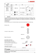
  Wire  rope  pulleys  must  be  installed  in  a 

position centrically to the rope drum. 

  In  order  to  ensure  correct  winding  up  of  the 

wire  rope  on  the  drum,  the  max.  wire  rope 
deflection angle must not be exceeded. 

  maximum wire rope deflection angle 


4° for standard wire ropes 


2°  for  non-twisting  resp.  twist-resistant wire 

ropes 

  The  minimum  dimension  (M)  from  the  drum 

until the middle  of the pulley must be adhered 
to. 


Illustration 7 


NOTICE!


Should the drum be extended and for some models with limit switch, the distance "M" must be increased. 
Standard values: 

15 x 1/2 drum length for standard wire ropes 

30 x 1/2 drum length for twist-resistant or non-twisting wire ropes 


6.5.1 

Wire rope pulley (provided by the customer) 

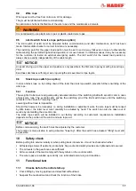
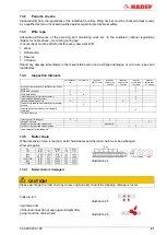
Table dimension "M" for standard drum length 

Type 

 "M "min 

1506, 1515, 1516 

4,3 

2306, 2309, 2316 

4,5 

2406, 2409, 2416 

4,5 

3405, 3406, 3416 

4,6 

4107, 4108 

5,4 

5105, 5106 

6,1 

6105 

8,1 

7104 

8,8 


Содержание 42/87E

Страница 1: ...Rev 08 5 52 290 00 01 08 Electric Wire Rope Winch 42 87E Installation Operating and Maintenance Instructions...

Страница 2: ...usage life 4 2 Safety 4 2 1 Warning notice and symbols 4 2 2 Duty of care of the owner 4 2 3 Requirements for the operating personnel 5 2 4 Appropriate use 5 2 5 Basic safety measures 6 3 Transport an...

Страница 3: ...cts meet European Union requirements in particular the valided EU Machine Directive The entire company works acc to a certified quality assurance system as per ISO 9001 The production of components at...

Страница 4: ...ion Danger from electricity Danger from explosive area 2 2 Duty of care of the owner DANGER Failure to follow the instructions of this manual can lead to unpredictable hazards For any resulting damage...

Страница 5: ...y important for operating personnel that rarely uses the equipment i e for installation or maintenance work DANGER In order to avoid severe injury please pay attention to the following when using the...

Страница 6: ...components with new original spare parts Do not use a defective unit listen for abnormal operating noises In case of malfunctions stop the operation immediately and rectify the fault Report damage and...

Страница 7: ...s of weather such as rain hail snow direct sunshine dust etc we recommend to use a cover in parking position If the device is set up in a continuously humid environment with strong temperature fluctua...

Страница 8: ...nt lowering of the load after the push button has been released 4 4 Important components Standard 3 phase current motor Gear Type 1506 up to 4108 spur gear Type 5106 up to 7104 planetary gear NOTICE S...

Страница 9: ...disengaging clutch separates the drum from its drive The clutch is actuated by a hand lever which is locked by a spring pin Before operation this spring pin must be pulled by hand and hold until the...

Страница 10: ...2 6 5 1 81 340 4108 3200 32 30 8 2 2100 217 202 12 3 5 16 128 5 5 1 5 12 6 5 1 82 460 5106 5000 36 34 6 1 5 3300 243 232 8 2 5 20 200 5 5 1 5 12 6 5 1 82 600 6105 7500 50 46 6 1 5 5000 332 309 8 2 5 2...

Страница 11: ...on twisting or at least twist resistant wire ropes For several rope layers winded through the drum steel reinforced wire ropes WARNING It is not allowed to use plastic wire ropes or plastic coated wir...

Страница 12: ...2 rope layers remain on the drum when the wire rope is unwinded 6 5 Wire rope deflection Wire rope pulleys must be installed in a position centrically to the rope drum In order to ensure correct wind...

Страница 13: ...nding on the control module Emergency stop Illustration 8 Arrow keys Lifting Lowering Illustration 9 System start optional Illustration 10 Push button functions E Relieved push button stand still push...

Страница 14: ...ever The protection cover over the switch element must not be removed Illustration 14 Disengaging Pull out the locking button 1 Pull the disengaging lever 2 against spring tension Let the locking butt...

Страница 15: ...t must not be exceeded 9 Commissioning 9 1 General The operator of the unit is responsible for the entire system According to the Ordinance on Industrial Safety and Health a hazard analysis must be ca...

Страница 16: ...control switch than do not match to the wiring direction of the wire rope In this case the winch must be stopped immediately Exchange two phases of the main current supply Test the winding direction...

Страница 17: ...r and guide pulley actuates rotation of the switching shaft with eccentric disc in case of slack wire rope The eccentric disc pushes the switching pin of the limit switch down until the switching cont...

Страница 18: ...1 5 friction lining thickness 2306 FD 15 105 26 0 3 0 45 1 5 friction lining thickness 2316 FD 06S 180 40 0 4 0 55 1 5 friction lining thickness 2406 FD 15 105 26 0 3 0 45 1 5 friction lining thicknes...

Страница 19: ...k process Depending on the type of hoist the following variants are possible 12 4 1 Electronic hoisting power limiter as option except serial AT Power consumption of the hoist motor is measured during...

Страница 20: ...7 switching shaft Illustration 22 NOTICE Connection is normally effected in our factory it is shown in the diagram 12 6 2 Setting for wire rope exit exceeding 45 Further setting is necessary if the wi...

Страница 21: ...unction X X check brake air gap only for electric devices X check overload protection if existent X clean and lubricate the wire rope X X X check wire rope and wire rope end fastenings for damage and...

Страница 22: ...pe must be carried out in accordance with the currently valid ISO 4309 CAUTION In case of corrosion cracks or reaching the wear limit the affected rope must be replaced with a new original rope 14 2 G...

Страница 23: ...free Even very small amounts of dirt can reduce the braking moment considerably 14 4 Lubricant selection FUCHS SHELL ESSO ARAL MOBIL TOTAL CASTROL KL BER Renolin PG 220 Omala S4 WE 220 Glycolube 220...

Страница 24: ...manufactuerer for repair Rotor is rubbing Brake does not release See problem Brake does not release Defect of capacitor only for alternating current 1 Replace the capacitor Defect of starter relay on...

Страница 25: ...all operating material is disposed of in accordance with environmental regulations 17 1 Temporary decommissioning Measures are as above Also read the chapter Transport and storage 17 2 Final decommiss...

Отзывы: