22
Rossi
Operating instructions − UTD.045.06-2013.00_TR_EN
TR
EN
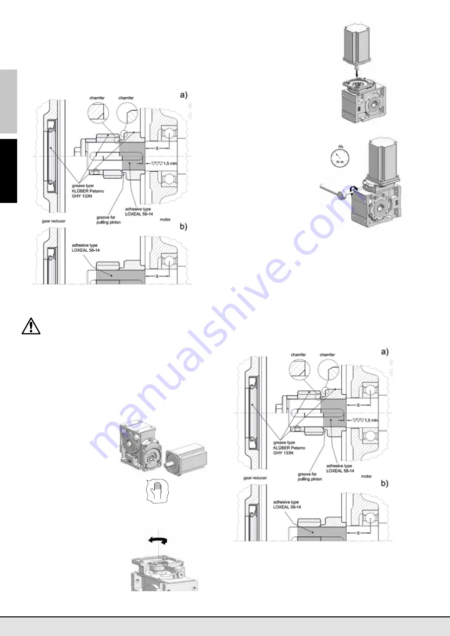
axial fastening
(fig. b), apply
adhesive type LOXEAL 58-14
also on the motor shaft part laying under the
pinion
;
– in case of axial fastening system with hub clamp and dowels,
make sure that they do not overhung from spacer external surfa-
ce: screw the dowels completely and, if necessary, imprint the
motor shaft with a point;
– grease (with grease type KLÜBER Petamo GHY 133N) the pinion
teeth, the seal ring rotary seating and the ring itself, and assemble
carefully,
taking care not to damage seal ring lip in case of
accidental shock with pinion toothing
.
9.5 - Servo motor mounting and dismounting
Attention! Excessive long and heavy motors may
cause critical conditions for bending torque and,
during running, abnormal vibrations
. In these cases,
it is advisable to adopt an adequate auxiliary motor
mounting system.
Servo gear reducer type MR (servo motor coupling of direct
type):
–
Worm servo gear reducer MR V
–
Helical servo gear reducer MR 2I
–
Bevel-helical servo gear reducer MR CI
The servo gear reducer input face has a servo motor mounting
flange,
including bolts,
a hollow high speed shaft provided with
axial slots and hub clamp.
This kind of fitting can be even
suitable for mounting servo
motors with keyless shaft
end
.
Prior to installation, throughly
clean and lubricate the mating
surfaces to avoid the risk of
seizing and fretting corrosion
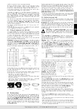
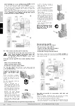
(see fig. 1).
For the servomotor mounting
proceed as follows:
–
when a lowered key is
needed, replace the key on the
servomotor shaft end with the
one supplied together with the
servo gear reducer; if necessary,
adjust it accordingly to the servo
motor shaft keyway length;
–
position the gear reducer
vertically with motor mounting
flange upwards (see fig. 2);
– rotate the hub clamp so that the
tightening screw head is aligned
with one of the input holes
present on gear reducer flange,
removing first the relevant plugs
(see fig. 2);
–
do not modify the factory setting of hub clamp axial position
fi g. 1
fi g. 2
as this is the best solution in
order to reach the maximum
tightening effect;
– introduce the motor from the top
down to shoulder (see fig. 3);
– lock the servomotor fasetning
bolts or nuts to the servo gear
reducer flange;
–
lock the hub clamp screw by
means of torque wrench until
the tightening torque stated in
the tightening torque table (at
page 24) is reached (also during
this operation it is advisable not
to modify the hub clamp axial
position, see fig. 4);
– screw the hole plugs of gear
reducer flange.
Before any motor dismounting
be sure that the hub clamp
tightening screw has been
unloosed, if present
.
Servo gear reducer type MR
(servo motor coupling of direct type)
–
Worm servo gear reducer MR IV
–
Coaxial servo gear reducer MR 2I, MR 3I
–
Helical servo gear reducer MR 3I
–
Bevel-helical servo gear reducer MR ICI
The servo gear reducer input face has a flange (
bolts included
) for
servo motor mounting and a helical pinion gear to be fitted onto the
servo motor shaft end.
Assembly not possible for servomotors with shaft end
without key
.
Prior to installation, thoroughly clean and lubricate the mating
surfaces to avoid the risk of seizing and fretting corrosion.
For the servo motor mounting proceed as follows:
– check that the fit-tolerance (standard locking) between hole and
shaft end is K6/j6 for D
≤
28 mm, J6/k6 for D
≥
38 mm; the length
fi g. 3
fi g. 4


