15
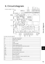
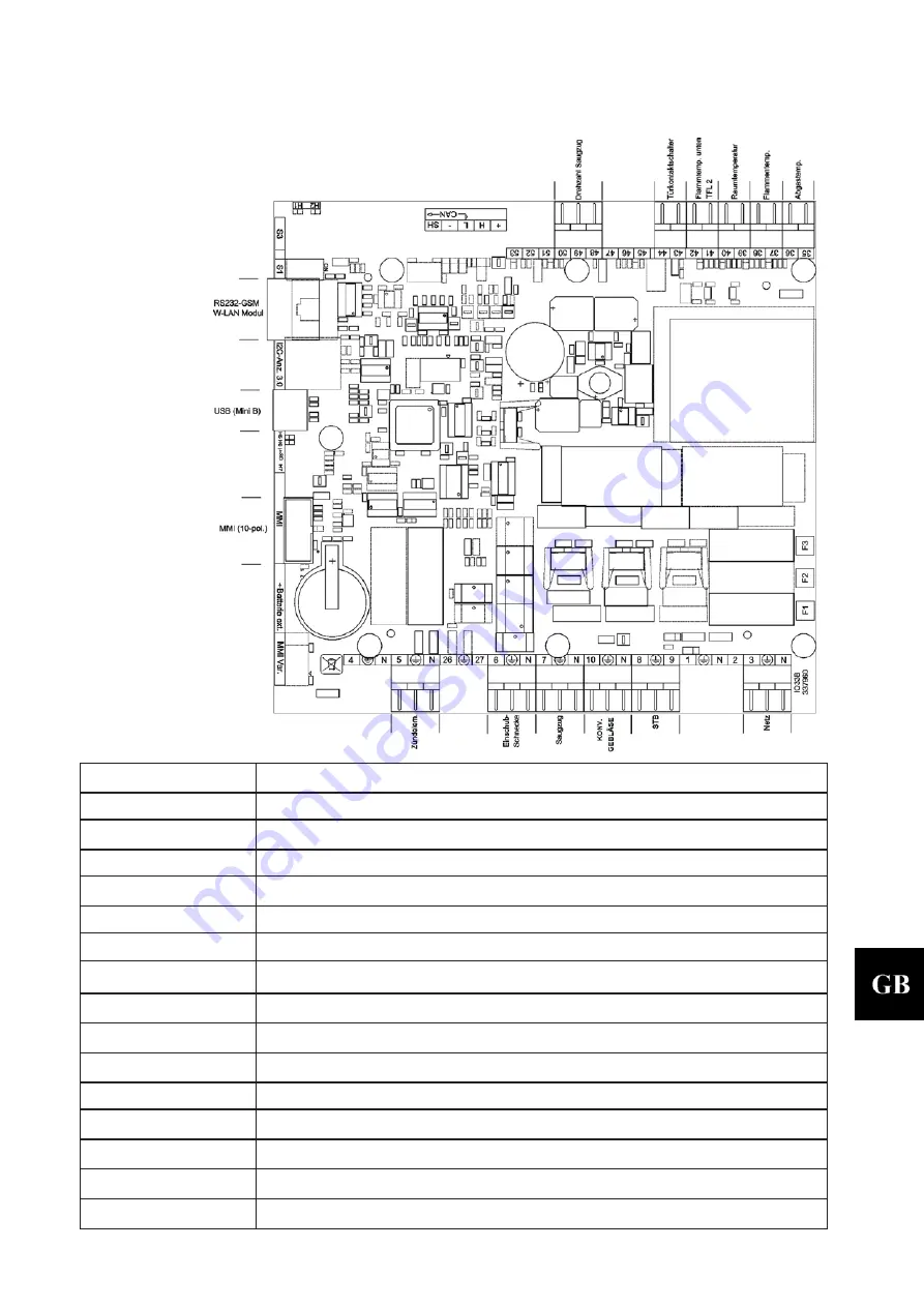
6. Circuit diagram
Connection diagram 10 33.3
Description connection diagram
:
No:
Description wiring harness
3
Power
plug/ mains filter
5
Electric ignition
6
Auger
7
Induced draught
8. IX
Safety temperature control
10.
CONV.FAN THS30B5/TFA745-S 5-PT160 HSP 7
35/36
Flue gas temperature sensor
37/38
Flame temperature sensor
39/40
Room temperature sensor
41/42
Flame temperature sensor bottom
43/44
Door contact switch
48-50
RPM flue gas fan
F1
Fuse T 3,15A ignition, induced draught fan, auger
F2
Fuse T 3,15A reserve
F3
Fuse T 0,315A control unit
C
ir
cu
it
d
iag
ram
Содержание 0545008000000
Страница 4: ......
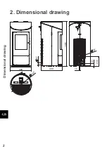
Страница 6: ...2 2 Dimensional drawing Dimensional drawing 1051 494 490 63 230 15 489 57 80 ...
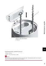
Страница 15: ...11 Maintenance works ...
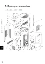
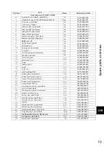
Страница 16: ...12 5 Spare parts overview 5 1 Complete list HSP 7 450 08 Spare parts overview ...
Страница 20: ...16 ...

