–
12
–
gB
9. reguLAr mAintenAnce worK
(DOCUMENT ACCORDING TO VEHICLE MANUFACTURER'S SPECIFICATION)
maintenance work
maintenance interval
execution
Visual inspection for
cracks and deforma-
tions
W1
Before every use
Immediately repair damaged rear support device, if necessary replace
Grease spindle nut and
spindle
W2
After 100
support operations
Regrease rear support device by means of grease nipple with min. 10 strokes. Extend and
retract in high gear over entire stroke at no load.
Wear test
Only use valid, unda-
maged gauges!
The manufacturer's
operating instructions
are decisive.
W3
After 500
support operations,
at the latest annually
Interim testing after
special incidents neces-
sary (e.g.landslide or
sluggishness)
Dismantle support tube
Establish ground clearance of min. 630 mm
Remove nuts with interposed locking washer (Nord-Lock). Completely extend the
support tube in high gear using the crank handle, with the aid of a second person hold
support tube (approx. 13 kg) at the stroke end and remove.
Danger of falling
!
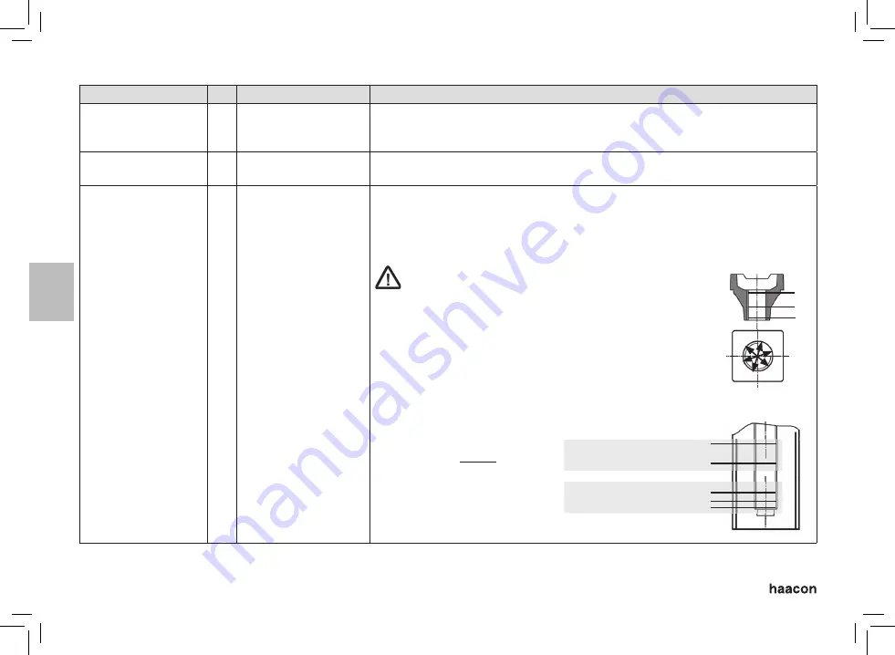
Visually inspect the spindle nut for damage and corrosion of internal
thread. Calibrate calliper (order No. 126 668) with ring gauge to ‚0‘
following manufacturer's instructions.
Carry out 9 measurements according to adjoining sketch
Admissible tolerance against ring gauge 1.0 mm.
Visually inspect the spindle for damage and corrosion
Calibrate calliper (order No. 126 668) with ring gauge to ‚0‘ in the spe-
cifi ed calibrating range following manufacturer's instructions.
Carry out 3 measurements within the measuring range according to
adjoining sketch. Admissible tolerance to calibration 1.0 mm.
worn, damaged or severely
corroded parts always have to
be replaced together with their
counterpart.
1
2
3
140
100
20
10
0
Calibration range
Measuring range


