9
2
Installing the firewall
WARNING!
Keep the tamper-proof seal on a mounting screw on the chassis cover intact, and if you want to open
the chassis, contact H3C for permission. Otherwise, H3C shall not be liable for any consequence.
The firewall view varies by model. The following figures are for illustration only. This document uses
an F1080 firewall as an example.
Installation flow
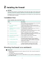
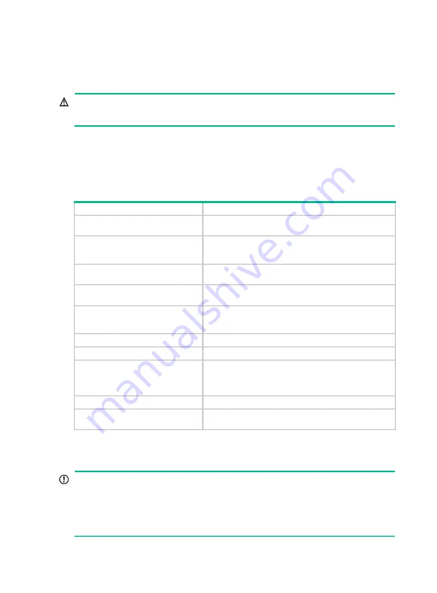
Table2-1 Installation flow for the F10X0 firewalls
Step
Description
1.
Start
Before installation, make sure all requirements on the checklist
are met and the firewall is powered off.
Mounting the firewall on a
workbench
Verify that the workbench is sturdy and reliably grounded.
Ensure a minimum clearance of 100 mm (3.94 in) around the air
inlet and outlet vents of the chassis.
Installing the firewall in a standard
19-inch rack
To avoid bodily injury and device damage, use a minimum of
two people to rack-mount the device.
4.
Before installation, make sure the firewall and rack are reliably
grounded and you wear an ESD wrist strap.
5.
Before you install a power module, make sure the power
module is not connected to any power source and the grounding
cable of the firewall is connected reliably.
6.
Installing an interface module
Install compatible interface modules on the firewall.
7.
Install compatible drives on the firewall.
8.
The firewall provides various ports. Choose compatible
transceiver modules and cables as required. To avoid bodily
injury or device damage, read the restrictions and guidelines
carefully before connection.
9.
Connect compatible power cords to the power modules.
10.
Verify that the firewall is installed securely and reliably
grounded, and that the power modules are as required.
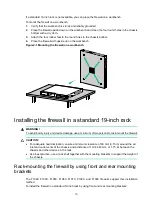
Mounting the firewall on a workbench
IMPORTANT:
•
Ensure good ventilation and a minimum clearance of 100 mm (3.94 in) around the chassis for
heat dissipation.
•
Avoid placing heavy objects on the firewall.
•
To stack firewalls, make sure a minimum vertical distance of 15 mm (0.59 in) is available between
two adjacent firewalls.

