background image


9-60 

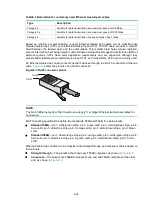
Table9-3 Description for commonly used Ethernet twisted pair cables 

Type 

Description 

Category 5 

Suitable for data transmission at a maximum speed of 100 Mbps 

Category 5e 

Suitable for data transmission at a maximum speed of 1000 Mbps 

Category 6 

Suitable for data transmission at a speed higher than 1 Gbps 


Based on whether a metal shielding is used, Ethernet twisted pair cables can be classified into 
shielded twisted pair (STP) and unshielded twisted pair (UTP). An STP cable  provides a metallic 
braid between the twisted pairs and the outer jacket. This metallic braid helps reduce radiation, 
prevent information from being listened, and eliminate external electromagnetic interference (EMI) of 
external sources. STPs have strict application requirements and are expensive although they 
provide better EMI prevention performance than UTPs, so in most LANs, UTPs are commonly used.  

An Ethernet twisted pair cable connects network devices through the RJ-45 connectors at the two 
ends. 

Figure9-3

 shows the pinouts of an RJ-45 connector.  

Figure9-3 RJ-45 connector pinout 


NOTE: 

The RJ-45 Ethernet ports of the firewall use category 5 or higher Ethernet twisted pair cables for 
connection.  


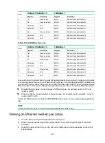
EIA/TIA cabling specifications define two standards, 568A and 568B, for cable pinouts.  


Standard 568A

—pin 1: white/green stripe, pin 2: green solid, pin 3: white/orange stripe, pin 4: 

blue solid, pin 5: white/blue stripe, pin 6: orange solid, pin 7: white/brown stripe, pin 8: brown 
solid.  


Standard 568B

—pin 1: white/orange stripe, pin 2: orange solid, pin 3: white/green stripe, pin 4: 

blue solid, pin 5: white/blue stripe, pin 6: green solid, pin 7: white/brown stripe, pin 8: brown 
solid.  

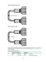
Ethernet twisted pair cables can be classified into straight-through and crossover cables based on 
their pinouts.  


Straight-through

—The pinouts at both ends are T568B compliant, as shown i

Figure9-4


Crossover

—The pinouts are T568B compliant at one end and T568A compliant at the other 

end, as shown in 

Figure9-5


PIN #8

PIN #1

Содержание SecPath F10X0

Страница 1: ...H3C SecPath F10X0 Firewalls Installation Guide New H3C Technologies Co Ltd http www h3c com Document version 6W105 20220215...

Страница 2: ...may be mentioned in this manual are the property of their respective owners Notice The information in this document is subject to change without notice All contents in this document including stateme...

Страница 3: ...replace with actual values Square brackets enclose syntax choices keywords or arguments that are optional x y Braces enclose a set of required syntax choices separated by vertical bars from which you...

Страница 4: ...work device such as a router switch or firewall Represents a routing capable device such as a router or Layer 3 switch Represents a generic switch such as a Layer 2 or Layer 3 switch or a router that...

Страница 5: ...ardware model configuration or software version It is normal that the port numbers sample output screenshots and other information in the examples differ from what you have on your device Documentatio...

Страница 6: ...er modules 16 Installing a power module for an F1070 or F1080 firewall 16 Installing a power module for an F1090 firewall 17 Installing an interface module 18 Installing a drive 19 Connecting Ethernet...

Страница 7: ...6 41 Configuration terminal display problem 6 41 Password loss 6 41 Cooling system failure 6 42 Software loading failure 6 42 7 Appendix A Chassis views and technical specifications 7 43 Chassis view...

Страница 8: ...iii Ethernet twisted pair cable 9 59 Introduction 9 59 Making an Ethernet twisted pair cable 9 62 Optical fiber 9 63...

Страница 9: ...nderstood or followed can result in data loss data corruption or damage to hardware or software General safety recommendations Do not place the firewall on an unstable case or desk The firewall might...

Страница 10: ...emit invisible laser light Do not stare into beams or view directly with optical instruments when the firewall is operating The firewall is a Class 1 laser device Before you disconnect the fiber conn...

Страница 11: ...in the equipment room Lasting high relative humidity can cause poor insulation electricity leakage mechanical property change of materials and metal corrosion Lasting low relative humidity can cause...

Страница 12: ...the air inlet and outlet vents of the chassis 19 inch rack mounting Ensure a minimum clearance of 80 mm 3 15 in around the air inlet and outlet vents of the chassis and a distance of 1U 44 45 mm or 1...

Страница 13: ...es only indoors If part of the network cable of an Ethernet port must be routed outdoors connect a lightning arrester to the cable before you plug the cable into the port Lightning protection To prote...

Страница 14: ...ied for other models Rubber feet Power cord retainer clip Power cord Grounding cable Console cable Pre installation checklist Table1 4 Checklist before installation Item Requirements Result Installati...

Страница 15: ...grid system Separate the protection ground of the firewall from the grounding device or lightning protection grounding device as far as possible Keep the firewall far away from radio stations radar a...

Страница 16: ...8 Item Requirements Result accessories User supplied tools Reference Documents shipped with the firewall Online documents...

Страница 17: ...ll and rack are reliably grounded and you wear an ESD wrist strap 5 Installing power modules Before you install a power module make sure the power module is not connected to any power source and the g...

Страница 18: ...ard 19 inch rack WARNING To avoid bodily injury and device damage use a minimum of two persons to rack mount the firewall CAUTION For adequate heat dissipation ensure a minimum clearance of 80 mm 3 15...

Страница 19: ...ith the firewall Figure2 3 Attaching mounting brackets and shoulder screws to the firewall 6 Attach the rear mounting brackets to the rear rack posts The rear mounting brackets can be attached to the...

Страница 20: ...ing brackets with the wide flange inside the rack Figure2 5 Attaching the rear mounting brackets with the wide flange outside the rack 7 Mount the firewall in the rack Use M6 screws to secure the moun...

Страница 21: ...firewall by using front mounting brackets The F1005 and F1010 firewalls support this installation method To install the firewall in a standard 19 inch rack by using front mounting brackets 1 Wear an E...

Страница 22: ...ing brackets to both sides of the firewall with M4 screws provided with the firewall Figure2 9 Attaching the front mounting brackets to the firewall 6 Mount the firewall in the rack Use M6 screws to s...

Страница 23: ...all with a grounding strip If a grounding strip is available at the installation site connect the grounding cable through the grounding strip To connect the grounding cable 1 Remove the grounding scre...

Страница 24: ...f the grounding cable Attach the hook to the grounding point and secure the hook with the screw Figure2 12 Grounding the firewall with the grounding terminal on the rack Installing power modules CAUTI...

Страница 25: ...er module slowly into the slot along the guide rails 3 Use a Phillips screwdriver to fasten the captive screws on the power module to secure the power module in place Figure2 14 Installing a power mod...

Страница 26: ...ejector levers of the interface module while inserting it into an upper slot The F1005 and F1010 do not support interface modules No interface modules are provided with the firewall Purchase them as n...

Страница 27: ...e drives from other vendors Purchase drives from H3C as needed To install a drive 1 Wear an ESD wrist strap and make sure it makes good skin contact and is reliably grounded 2 Remove the filler panel...

Страница 28: ...nd clean Make sure the fiber connector matches the transceiver module Before connecting a fiber make sure the optical power at the receiving end does not exceed the transceiver module s upper threshol...

Страница 29: ...iber connector 4 Identify the Rx and Tx ports on the transceiver module Plug one end of the optical fiber into the transceiver module in the firewall and plug the other end into the transceiver module...

Страница 30: ...the power receptacle 4 Connect the other end of the power cord to an AC power source Figure2 23 Connecting an AC power cord for an F1005 or F1010 firewall Connecting an AC power cord for an F1020 F103...

Страница 31: ...ord 2 Connect the other end of the power cord to an AC power source Figure2 26 Connecting an AC power cord using a power cord retainer clip to secure the power cord Figure2 27 Connecting an AC power c...

Страница 32: ...rd connector with a flathead screwdriver to secure the power cord connector 3 Use a cable tie to secure the power cord to the handle 4 Connect the other end of the power cord to a DC power source Figu...

Страница 33: ...ipation around the firewall The firewall and its components are installed securely The screws are fastened tightly The power source specifications are as required by the firewall The grounding cable a...

Страница 34: ...the serial console port or micro USB console port you must run a terminal emulator program TeraTermPro or PuTTY on your configuration terminal and configure the following settings for the terminal Fo...

Страница 35: ...Normal Extended BootWare The Extended BootWare is self decompressing Done H3C F1080 BootWare Version 1 04 Compiled Date Sep 10 2014 CPU Type xxx CPU Clock Speed 1000MHz Memory Type DDR3 SDRAM Memory S...

Страница 36: ...own Answer tests in the engine Known answer test for SHA1 passed Known answer test for HMAC SHA1 passed Known answer test for AES passed Known answer test for RSA signature verification passed Known a...

Страница 37: ...st use a different IP address than the Ethernet management interface 3 Start a browser enter 192 168 0 1 in the address bar and press Enter 4 Enter the default username admin and password admin and th...

Страница 38: ...replace a power module for an F1070 or F1080 firewall 1 Face the rear panel of the firewall 2 Use a Phillips screwdriver to loosen the captive screw of the power module 3 Hold the power module with on...

Страница 39: ...e an interface module To install two or more interface modules use the upper interface module slots as a best practice If you have installed an interface module in a lower slot you must press down the...

Страница 40: ...side of the drive panel to release the locking lever 4 Hold the locking lever and pull the drive out of the slot 5 Install a new drive For the installation procedure see Installing a drive Figure4 4...

Страница 41: ...tall dust caps to the LC connectors 3 Pivot the clasp of the transceiver module down to the horizontal position and gently pull the transceiver module out Figure4 6 Removing the transceiver module 4 I...

Страница 42: ...FCard Num 0 Displaying the software and hardware version information for the firewall Use the display version command to display software and hardware version information for the firewall Sysname disp...

Страница 43: ...NUFACTURING_DATE 2016 04 29 VENDOR_NAME H3C Fan 0 The operation is not supported on the specified fan Fan 1 The operation is not supported on the specified fan Fan 2 The operation is not supported on...

Страница 44: ...t memory is measured in KB Slot 1 Total Used Free Shared Buffers Cached FreeRatio Mem 1718140 921604 796536 0 1108 187644 46 4 Buffers Cache 732852 985288 Swap 0 0 0 Table5 3 Output description Field...

Страница 45: ...rature information of the firewall IMPORTANT Only F1020 F1030 F1050 F1060 F1070 F1080 and F1090 firewalls support the display environment command Use the display environment command to display the tem...

Страница 46: ...ave or display diagnostic information Y save N display Y N y Please input the file name gz flash diag gz Diagnostic information is outputting to flash diag gz Please wait Save successfully To view the...

Страница 47: ...firewall prompts REBOOT IN ONE MINUTE and reboots in one minute If you are performing file operations when the firewall is to be rebooted the system does not execute the reboot command for security T...

Страница 48: ...5 40 Task Command Remarks and specify a reboot waiting time scheduler reboot delay...

Страница 49: ...ssue 1 Verify that the power supply system is operating correctly 2 Verify that the serial console cable or micro USB console cable is correctly connected 3 Verify that the serial console cable or mic...

Страница 50: ...formation about the firewall temperature in the display environment command output varies by firewall model Only F1020 F1030 F1050 F1060 F1070 F1080 and F1090 firewalls support the display environment...

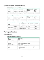
Страница 51: ...ne console port One drive slot Figure7 1 Front panel 1 Drive slot 2 Console port 3 USB ports host mode Type A connector 4 Combo interfaces 5 Bypass ports 6 10 100 1000BASE T copper ports 7 LEDs 8 Mana...

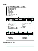
Страница 52: ...receptacle 2 Interface module slot 1 3 Interface module slot 2 not supported 4 Grounding screw F1030 F1050 F1060 The F1030 F1050 or F1060 firewall provides the following ports on the front panel Sixt...

Страница 53: ...BASE T autosensing Ethernet copper ports Eight 1000BASE X fiber ports Two 10GBASE R fiber ports Two USB ports One console port Two drive slots Figure7 7 Front panel 1 Drive slots 2 LEDs 3 10 100 1000B...

Страница 54: ...Management Ethernet port 1 MGMT 3 10 100 1000BASE T copper ports 4 10GBASE R fiber ports 5 1000BASE X fiber ports 6 LEDs 7 Reset button 8 Micro USB port 9 USB port host mode Type A connector 10 Conso...

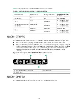
Страница 55: ...00 1000BASE T Ethernet copper ports When the firewall is operating correctly the four ports operate as common data ports When the firewall is powered off the four ports are divided into two bypass por...

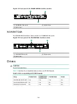
Страница 56: ...the NS NIM TG6A interface module 1 10GBASE R fiber ports 2 Captive screw 3 Ejector lever Drives CAUTION Do not hot swap drives Table7 2 describes the compatibility between drives and F10X0 firewalls...

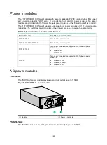
Страница 57: ...sure they are the same model Table7 3 Power modules available for the firewall Firewall model Available power modules F1005 F1010 One built in power module F1020 F1030 F1050 F1060 Two built in power...

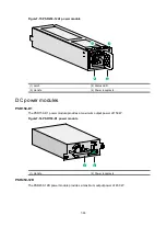
Страница 58: ...e 4 Power receptacle DC power modules PSR150 D1 The PSR150 D1 power module provides a maximum output power of 150 W Figure7 16 PSR150 D1 power module 1 Handle 2 Power receptacle PSR450 12D The PSR450...

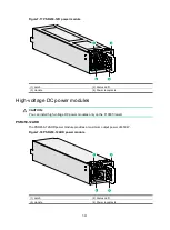
Страница 59: ...voltage DC power modules CAUTION You can install high voltage DC power modules only on the F1090 firewall PSR450 12AHD The PSR450 12AHD power module provides a maximum output power of 450 W Figure7 1...

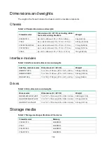
Страница 60: ...modules Table7 5 Interface module dimensions and weights Interface module model Dimensions H W D Weight NSQM1GT4PFC 19 150 172 9 mm 0 75 5 91 6 81 in 0 45 kg 0 99 lb NSQM1GP4FBA 19 150 172 9 mm 0 75...

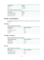
Страница 61: ...sis and the removable components Chassis Table7 9 Chassis power consumption Firewall model Power consumption F1005 F1010 32 W F1020 F1030 F1050 F1060 79 W F1070 F1080 116 W F1090 180 W Interface modul...

Страница 62: ...50 W Table7 14 High voltage DC power module specifications Model Rated input voltage range Maximum input current Maximum power PSR450 12AHD AC input 100 VAC to 240 VAC 50 Hz or 60 Hz 7 A 450 W High vo...

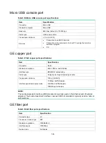
Страница 63: ...ard compliance 802 3 802 3u and 802 3ab Interface type MDI MDI X autosensing Cable type Category 5 or higher twisted pair cable Transmission distance 100 m 328 08 ft Interface speed and duplex mode 10...

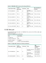
Страница 64: ...M1550 1550 nm LC 9 125 m single mode optical fiber 100 km 62 14 miles 10 GE fiber port The F1070 F1080 firewall provides two 10GBASE R fiber ports and the F1090 provides eight 10GBASE R fiber ports Ta...

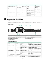
Страница 65: ...er port LED 4 1000BASE X fiber port LED 5 10GBASE R fiber port LED 6 Interface module LED 7 Power module LED Table8 2 LED description LED Mark Status Description System status LED SYS Off The firewall...

Страница 66: ...correctly Power module LED PWR0 PWR1 Off No power module is present or the power module has failed Steady green The power module is operating correctly 9 Appendix C Cables Console cable RJ 45 to DB9...

Страница 67: ...es a different color and has a diameter of about 1 mm 0 04 in A pair of twisted copper cables can cancel the electromagnetic radiation of each other and reduce interference of external sources An Ethe...

Страница 68: ...n Ethernet twisted pair cable connects network devices through the RJ 45 connectors at the two ends Figure9 3 shows the pinouts of an RJ 45 connector Figure9 3 RJ 45 connector pinout NOTE The RJ 45 Et...

Страница 69: ...Pin 10BASE T 100BASE TX 1000BASE T Signal Function Signal Function 1 Tx Sends data BIDA Bi directional data cable A Straight through cable white orange orange white green blue white blue green white b...

Страница 70: ...a cable C To ensure normal communication the pins for sending data on one port must correspond to the pins for receiving data on the peer port When both of the ports on the two devices are MDI or MDIX...

Страница 71: ...t source and transmission distance Uses lasers as the light source often within campus backbones for distance of several thousand meters Uses LEDs as the light source often within LANs or distances of...

Страница 72: ...two fiber connectors You can brush the end faces only in one direction Never bend or curve a fiber when connecting it If the fiber has to pass through a metallic board hole when passing through a met...

Отзывы: