297
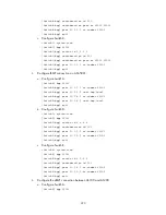
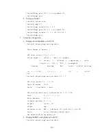
[SwitchC-ospf-1] quit
c.
Configure Switch D.
<SwitchD> system-view
[SwitchD] ospf
[SwitchD-ospf] area 0
[SwitchD-ospf-1-area-0.0.0.0] network 194.1.1.0 0.0.0.255
[SwitchD-ospf-1-area-0.0.0.0] network 195.1.1.0 0.0.0.255
[SwitchD-ospf-1-area-0.0.0.0] quit
[SwitchD-ospf-1] quit
3.
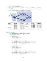
Configure BGP connections.
a.
Configure Switch A.
<SwitchA> system-view
[SwitchA] bgp 100
[SwitchA-bgp] peer 192.1.1.2 as-number 200
[SwitchA-bgp] peer 193.1.1.2 as-number 200
b.
Inject network 1.0.0.0/8 to the BGP routing table on Switch A.
[SwitchA-bgp] network 1.0.0.0 8
[SwitchA-bgp] quit
c.
Configure Switch B.
[SwitchB] bgp 200
[SwitchB-bgp] peer 192.1.1.1 as-number 100
[SwitchB-bgp] peer 194.1.1.1 as-number 200
[SwitchB-bgp] quit
d.
Configure Switch C.
[SwitchC] bgp 200
[SwitchC-bgp] peer 193.1.1.1 as-number 100
[SwitchC-bgp] peer 195.1.1.1 as-number 200
[SwitchC-bgp] quit
e.
Configure Switch D.
[SwitchD] bgp 200
[SwitchD-bgp] peer 194.1.1.2 as-number 200
[SwitchD-bgp] peer 195.1.1.2 as-number 200
[SwitchD-bgp] quit
4.
Configure attributes for route 1.0.0.0/8, making Switch D give priority to the route learned
from Switch C.
Configure a higher MED value for the route 1.0.0.0/8 advertised from Switch A to peer
192.1.1.2.
a.
Define an ACL numbered 2000 to permit route 1.0.0.0/8.
[SwitchA] acl number 2000
[SwitchA-acl-basic-2000] rule permit source 1.0.0.0 0.255.255.255

