145
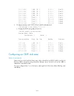
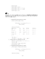
10.2.1.0/24 3 Transit 10.2.1.2 10.2.1.1
0.0.0.1
10.3.1.0/24 7 Inter 10.2.1.1 10.2.1.1
0.0.0.1
10.4.1.0/24 3 Stub 10.4.1.1 10.4.1.1
0.0.0.1
10.5.1.0/24 17 Inter 10.2.1.1 10.2.1.1
0.0.0.1
10.1.1.0/24 5 Inter 10.2.1.1 10.2.1.1
0.0.0.1
Routing for ASEs
Destination Cost Type Tag NextHop
AdvRouter
3.1.2.0/24 1 Type2 1 10.2.1.1
10.5.1.1
Total Nets: 6
Intra Area: 2 Inter Area: 3 ASE: 1 NSSA: 0
In the previous configuration procedure output, because Switch C resides in a normal OSPF area, its
routing table contains an external route.
4.
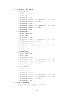
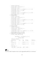
Configure Area 1 as a stub area.
a.
Configure Switch A.
[SwitchA] ospf
[SwitchA-ospf-1] area 1
[SwitchA-ospf-1-area-0.0.0.1] stub
[SwitchA-ospf-1-area-0.0.0.1] quit
[SwitchA-ospf-1] quit
b.
Configure Switch C.
[SwitchC] ospf
[SwitchC-ospf-1] area 1
[SwitchC-ospf-1-area-0.0.0.1] stub
[SwitchC-ospf-1-area-0.0.0.1] quit
[SwitchC-ospf-1] quit
c.
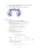
Display OSPF routing information on Switch C.
[SwitchC] display ospf routing
OSPF Process 1 with Router ID 10.4.1.1
Routing Tables


