background image

Installation Manual 
H3C SecPath F1000-A Firewall 

Chapter 8  Multifunctional Interface Modules


8-10 

Attribute 

1GBE 

2GBE 

Operating mode 

10/100/1000 Mbps, auto-sensing 
Full-/half-duplex autonegotiation 


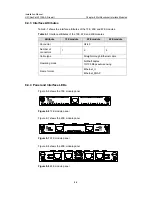
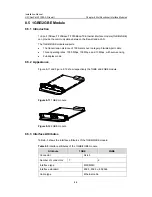
8.5.4  Panel and Interface LEDs 

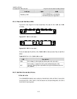
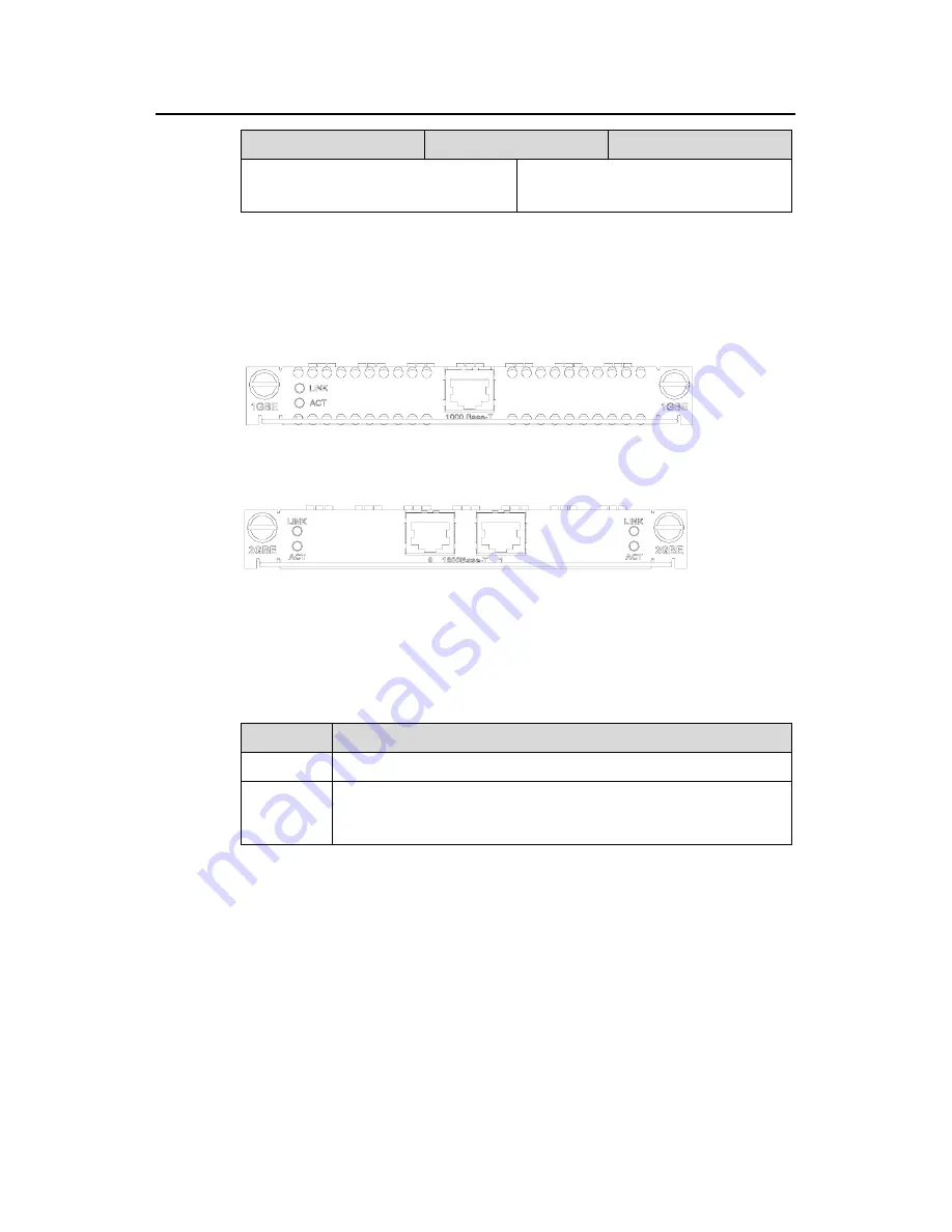
Figure 8-13 and Figure 8-14 show respectively the panel of the 1GBE and 2GBE 
modules. 


Figure 8-13 

1GBE module panel 


Figure 8-14 

2GBE module panel 

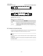
Table 8-6 describes the LEDs on the 1GBE/2GBE module panel and how to read their 
status. 

Table 8-6 

LEDs on the 1GBE/2GBE module 

LED 

Description 

LINK 

OFF means no link is present; ON means a link is present. 

ACT 

OFF means no packets are being transmitted/received on the 
interface; blinking means packets are being transmitted/received on 
the interface. 


8.5.5  Interface Connection Cable 

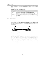
I. Ethernet cable 

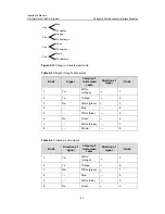
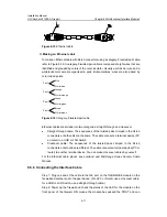
The 1GBE/2GBE module uses a category-5 twisted-pair cable with RJ-45 connectors 
(see Figure 8-15). Pins 1 and 2 of the connectors are for transmitting data, and Pins 3 
and 6 are for receiving data. 

Содержание H3C SECPATH F1000-A

Страница 1: ...H3C SecPath F1000 A Firewall Installation Manual Hangzhou H3C Technologies Co Ltd http www h3c com Manual Version T2 08044H 20070622 C 1 03...

Страница 2: ...InnoVision and HUASAN are trademarks of Hangzhou H3C Technologies Co Ltd All other trademarks that may be mentioned in this manual are the property of their respective owners Notice The information i...

Страница 3: ...Products Web Based Configuration Manual It directs users to configure the H3C SecPath Series Firewalls in Web mode Organization H3C SecPath F1000 A Firewall Installation Manual is organized as follows...

Страница 4: ...a command line are in Boldface italic Command arguments are in italic Items keywords or arguments in square brackets are optional x y Alternative items are grouped in braces and separated by vertical...

Страница 5: ...Create Folder III Symbols Convention Description Warning Means reader be extremely careful Improper operation may cause bodily injury Caution Means reader be careful Improper operation may cause data...

Страница 6: ...ng Rack 2 3 2 2 Safety Precautions 2 3 2 3 Unpacking Check 2 4 2 4 Tools Meters and Devices 2 4 Chapter 3 Hardware Installation 3 1 3 1 Installation Procedure 3 1 3 2 Mounting the Device 3 2 3 2 1 Tab...

Страница 7: ...6 3 Replacing a DDR SDRAM 6 2 6 3 1 Locating the DDR SDRAMs on the Mainboard 6 4 6 3 2 Removing a DDR SDRAM 6 5 6 3 3 Installing a DDR SDRAM 6 6 6 4 Closing the Chassis Cover 6 6 6 5 Replacing an MIM...

Страница 8: ...12 8 6 1 Introduction 8 12 8 6 2 Appearance 8 12 8 6 3 Interface Attributes 8 13 8 6 4 Panel and Interface LEDs 8 13 8 6 5 Interface Connection Fiber Cable 8 14 8 6 6 Connecting the Interface Fiber Ca...

Страница 9: ...erial interface 4 2 Figure 4 4 Set communications parameters 4 3 Figure 4 5 Settings tab 4 4 Figure 5 1 Send File dialog box 5 4 Figure 5 2 Sending File interface 5 4 Figure 5 3 Set up an environment...

Страница 10: ...9 Figure 8 12 2GBE module 8 9 Figure 8 13 1GBE module panel 8 10 Figure 8 14 2GBE module panel 8 10 Figure 8 15 Ethernet cable 8 11 Figure 8 16 Category 5 twisted pair cable 8 11 Figure 8 17 1GEF modu...

Страница 11: ...2 2 Limit to the content of dust in an equipment room 2 2 Table 2 3 Limits on the contents of harmful gases in the equipment room 2 2 Table 3 1 Dimensions of the firewall 3 2 Table 6 1 Memory specifi...

Страница 12: ...ists ACLs to implement dynamic packet filtering It provides various intelligent analysis and management methods supports email alarming and multiple logs and provides network management monitoring to...

Страница 13: ...North America Europe Australia and Japan the SecPath Series Firewall complies with the requirements of these countries and regions in EMC safety and network access 1 2 Hardware Features 1 2 1 Appeara...

Страница 14: ...SRAM stores the communication data with the CPU and running system Flash memory stores application files exceptional information and configuration files Boot read only memory Boot ROM stores the boots...

Страница 15: ...ts are being transmitted received on the interface 1 2 4 Attributes of the Fixed Interfaces I Console port CON Table 1 3 Attributes of the console port Attribute Description Connector RJ 45 Standard R...

Страница 16: ...are hot swappable The following table shows the Ethernet interface attributes of the H3C SecPath F1000 A Table 1 5 Attributes of the GE electrical interfaces Attribute Description Connector RJ 45 Int...

Страница 17: ...ical optical interfaces you need to first disable the rate and duplex mode configurations in the current mode electrical or optical and then configure the interface after the switchover 1 2 5 MIM The...

Страница 18: ...Installation Manual H3C SecPath F1000 A Firewall Chapter 1 Product Overview 1 7...

Страница 19: ...CMOS circuit of the product The higher the temperature is the greater the damage to your device Long lasting high temperature can speed up the aging of the insulation materials greatly lower the devic...

Страница 20: ...ESD preventive the card circuits and even the device can be badly damaged when excessive static electricity is present On the communication network connected to your device the static electricity mai...

Страница 21: ...esistant your device can get damaged when excessive lightning is present To protect your device against lightning z Ensure the chassis is connected to the earth ground z Ensure the earth point of the...

Страница 22: ...Tx port or the optical connector connected to it z You are recommended to use Uninterrupted Power Supply UPS for the firewall 2 3 Unpacking Check Check the arrived shipment against the packing list m...

Страница 23: ...Connect the power cord Connect the console terminal to device Verify the installation Power up the device Troubleshooting Power down the device Verify the installation Install MIM optional Power down...

Страница 24: ...adequate ventilation z Do not place any heavy stuff on the device 3 2 2 Rack Mounting the Device The firewall can be placed in a 19 inch standard rack The following table shows its dimensions Table 3...

Страница 25: ...ng Wires Caution When installing or using your device properly connect the grounding wire for lightning protection and anti interference The H3C SecPath Series Firewall provides a grounding screw whic...

Страница 26: ...ng protection make sure that your device has a good ground connection when it is operating 3 5 Connecting to the Console Terminal I Console port On the H3C SecPath Series Firewalls one RS 232 asynchro...

Страница 27: ...wer up the devices The console terminal shows the startup information of the firewall if the connection is correct For details see Chapter 4 Booting and Configuration 3 6 Connecting the Ethernet Inter...

Страница 28: ...er connectors All the optical transceivers are hot swappable Note A fiber connector as defined by the International Telecommunications Union ITU is a passive component that connects two or more fiber...

Страница 29: ...ult 1 Connect the Ethernet electrical port Caution Read the mark above the port to be connected carefully making sure it is the correct port Step 1 Connect one end of the Ethernet cable to the electri...

Страница 30: ...l and the Rx port on the peer device Step 2 Power up the firewall and check the status of the LINK LED of the Ethernet 1 interface On means the Rx link is present OFF means no Rx link is present check...

Страница 31: ...for example Step 1 Make sure that the grounding screw on the chassis is securely connected to the earth ground Step 2 Make sure that the power switches are placed in the OFF position Connect one end...

Страница 32: ...Caution Before connecting a DC input PSU read the label on the power cord to be used to make sure that you are using a DC power cord Step 4 Place the PWR0 switch into the ON position Step 5 Place the...

Страница 33: ...nual H3C SecPath F1000 A Firewall Chapter 3 Hardware Installation 3 11 Note Installation verification is extremely important because the operations of the firewall depend on its stability grounding an...

Страница 34: ...on the firewall and the DB9 connector to the serial port on the console terminal as shown in Figure 4 1 To RS 232 serial interface PC H3C SecPath F1000 A To console port Figure 4 1 Local configuration...

Страница 35: ...Windows98 as follows 1 Select serial interface Select the serial interface to be used from the Connect using drop down list as shown in Figure 4 3 The serial interface selected here must be the one co...

Страница 36: ...s 8 z Parity None z Stop bits 1 z Flow control None Click OK and the HyperTerminal window appears Figure 4 4 Set communications parameters 3 Select emulation type Choose Properties Settings to enter t...

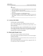
Страница 37: ...rectly connected z Proper power supply is used z The console cable is correctly connected z The console terminal or PC has been started and the related parameters have been set on it Caution Locate th...

Страница 38: ...rewall you can see the startup interface on the console terminal see the section 4 1 3 Booting Process After the system passes Power On Self Test POST press Enter as prompted When H3C is displayed you...

Страница 39: ...is ready for your configuration 4 2 Configuration Fundamentals 4 2 1 Basic Configuration Procedures Following are the basic steps that you can follow to configure your firewall Step 1 Figure out deta...

Страница 40: ...acert and ping z Have detailed debugging information for network troubleshooting z Enter a command by only entering the conflict free keyword portion because the CLI interpreter supports fuzzy keyword...

Страница 41: ...en boot the firewall Press Ctrl B when the system prompts Press Ctrl B to enter Boot Menu The system displays Please input Boot ROM password Caution z Press Ctrl B within three seconds after the promp...

Страница 42: ...for backward compatibility If you fails to upgrade the software because the system decides that you are using an invalid version even when the correct version is used you can use the option 7 to igno...

Страница 43: ...enter 1 to download an application program using XModem The firewall supports the following download speeds Downloading application program from serial Please choose your download speed 1 9600 bps 2...

Страница 44: ...box Step 5 Click Browse Select the application file to be downloaded and set protocol to XModem Click Send The following interface pops up Figure 5 2 Sending File interface Step 6 After completing the...

Страница 45: ...operation submenu to download the Boot ROM program using XModem Several speed options are available for you The subsequent steps are the same as those described in section I Upgrading an application...

Страница 46: ...essful the following message appears Writing to FLASH Please wait Backuping Boot ROM program to FLASH successed Step 3 When the Boot submenu appears again select 5 to exit and reboot the firewall II R...

Страница 47: ...Ethernet interface on the SecPath 1000F and set the path to the file to be downloaded z Configure the SecPath 1000F Step 1 Start the firewall and enter the Boot menu see section 5 1 1 Boot Menu Select...

Страница 48: ...m displays the following message and returns to the Net Port Download Menu Saving config please wait OK Net Port Download Menu 1 Change Net Parameter 2 Download From Net 3 Exit to Main Menu Enter your...

Страница 49: ...ll that is the put operation Download is to transfer files from the firewall to an FTP client that is the get operation I Setting up an uploading downloading environment z Set up a local uploading dow...

Страница 50: ...nment for remote uploading downloading using FTP Step 1 Connect the PC to an interface on the firewall through the WAN The PC and the firewall can reside on different network segments Step 2 Copy the...

Страница 51: ...set up an FTP connection with the firewall for example C version ftp 10 110 10 10 If the connection is set up the following message appears taking Windows98 for example Connected to 10 110 10 10 220 F...

Страница 52: ...l program from the root directory in the Flash and write it to the Boot ROM After that you have completed the upgrade of Boot ROM z After uploading the application program into the flash memory you ne...

Страница 53: ...ithin three seconds after the System starts booting prompt appears on the configuration terminal otherwise the system starts decompressing the program z You need to restart the firewall if you want to...

Страница 54: ...you can use this option to ignore the version check during a software upgrading Note that this option works only once when you select it The system resumes version check after you reboot the firewall...

Страница 55: ...power cords Step 2 Remove the interface cables from the front of the chassis except for the grounding wire Step 3 Place the firewall on a flat table with the rear forward Use a Phillips screwdriver t...

Страница 56: ...The company is not liable for any damage or consequence resulted from users operation without permission z Ensure that the firewall has no electricity before servicing the device to avoid bodily injur...

Страница 57: ...ll th DDR SD e new RAM Close the chassis Prepare the tools Start Complete h maint ardware enance Open the chassis Locate the DDR SDRAM Remove the old DDR SDRAM Install a new DDR SDRAM Close the chassi...

Страница 58: ...DDR SDRAM in a memory bank 6 3 1 Locating the DDR SDRAMs on the Mainboard When removing installing a DDR SDRAM make sure to identify the type of mainboard and the exact position of the DDR SDRAM See...

Страница 59: ...AM into a memory bank press the positioning recess into the pin in the bank 6 3 2 Removing a DDR SDRAM Step 1 Locate the DDR SDRAM to be replaced on the mainboard Step 2 Press the clips at both sides...

Страница 60: ...re 6 3 Step 2 Hold the DDR SDRAM by its non conductive top edge and place it in the desired memory bank Step 3 Exercise adequate pressure on the DDR SDRAM to press it into the bank Press the clips at...

Страница 61: ...ction 2 Install six screws at these places Figure 6 5 Close the chassis cover Step 5 Tighten the four captive screws that are removed in steps 3 and 4 described in section 6 2 Opening the Chassis Cove...

Страница 62: ...oes not light yet after you finish the above operations 7 2 Troubleshooting the Configuration System If the firewall is operating normally after it is powered up it displays the start up information o...

Страница 63: ...ing the Software Upgrade I Fault 1 1 Symptom Start the firewall and upgrade the Comware using TFTP The system displays Net Port Download Menu 1 Change Net Parameter 2 Download From Net 3 Exit to Main...

Страница 64: ...t the firewall and upgrade the Comware using TFTP The system displays Net Port Download Menu 1 Change Net Parameter 2 Download From Net 3 Exit to Main Menu Enter your choice 1 3 2 Starting the TFTP do...

Страница 65: ...nterface module 4FE z 1 port 10Base T 100Base T 1000Base TX Ethernet interface module 1GBE z 2 port 10Base T 100Base T 1000Base TX Ethernet interface module 2GBE z 1 port 1000Base LX 1000Base SX optic...

Страница 66: ...hassis until it is fully seated in the slot and its front panel is flush with the front of the chassis Step 4 Tighten the captive screws to secure the MIM Step 5 Power up the firewall and check the st...

Страница 67: ...firewall does not operate normally check that z Correct interface cables are used z The interfaces are working well by reading the interface LEDs z The configurations on the MIM are validated by exec...

Страница 68: ...ll Chapter 8 Multifunctional Interface Modules 8 4 Figure 8 3 1FE module II Appearance of the 2FE module Figure 8 4 shows the 2FE module Figure 8 4 2FE module III Appearance of the 4FE module Figure 8...

Страница 69: ...te 1FE module 2FE module 4FE module Connector RJ 45 Number of connectors 1 2 4 Cable type Straight through Ethernet cable Operating mode Full half duplex 10 100 Mbps auto sensing Frame format Ethernet...

Страница 70: ...ce 8 4 5 Interface Cable I Ethernet cable The FE modules use category 5 twisted pair cables with RJ 45 connectors see Figure 8 9 Pins 1 and 2 of the connectors are for transmitting data and Pins 3 and...

Страница 71: ...cabl Table 8 3 Straight through cable pinout RJ 45 Signal Category 5 twisted pair cable Direction of signal RJ 45 1 Tx White orange 1 2 Tx Orange 2 3 Rx White green 3 4 Blue 4 5 White blue 5 6 Rx Gree...

Страница 72: ...connects a terminal device PC or router to another terminal device You make crossover cables by yourself Note In making network cables shielded cables are preferred for the sake of electromagnetic co...

Страница 73: ...tegory 5 twisted pair cable z Three operating rates 1000 Mbps 100 Mbps and 10 Mbps with auto sensing z Full duplex mode 8 5 2 Appearance Figure 8 11 and Figure 8 12 show respectively the 1GBE and 2GBE...

Страница 74: ...describes the LEDs on the 1GBE 2GBE module panel and how to read their status Table 8 6 LEDs on the 1GBE 2GBE module LED Description LINK OFF means no link is present ON means a link is present ACT O...

Страница 75: ...d crossover z Straight through cable The sequences of the twisted pairs crimped in the RJ 45 connectors at both ends are the same The cable connects a terminal device PC or router to a HUB or LAN Swit...

Страница 76: ...ort 1000Base LX 1000Base SX Ethernet optical interface module 1GEF 2GEF can provide the communications between the firewall and a LAN The 1GEF 2GEF module can be multi mode short haul 850 nm single mo...

Страница 77: ...ong haul 1550 nm Min 9 5 dBm 9 dBm 2 dBm 4 dBm 4 dBm Trans mitter optical power Max 0 dBm 3 dBm 5 dBm 1 dBm 2 dBm Receiver sensitivity 17 dBm 20 dBm 23 dBm 21 dBm 22 dBm Central wavelength 850 nm 1310...

Страница 78: ...are being transmitted received on the interface blinking means packets are being transmitted received on the interface 8 6 5 Interface Connection Fiber Cable You can select the corresponding the fibe...

Страница 79: ...the module and the other end into the Tx port on the peer device Plug one end of another fiber cable into the Tx port on the module and the other end into the Rx port on the peer device Step 3 Power...

Страница 80: ...MAC SHA 1 8 7 4 Panel and Module LEDs Figure 8 22 shows the panel of the SSL module Figure 8 22 SSL module panel Table 8 10 LEDs on the SSL module LED Description STATUS OFF means the module is not po...

Страница 81: ...uring the booting of the firewall Solution The ACTIVE LED should blink for two seconds and then become OFF during the booting of the firewall Solid OFF means that the module initialization fails The p...

Отзывы: