


Installation Manual
H3C SecPath F100-A Firewall
Chapter 7 MIM Modules
7-7
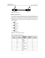
Table 7-4
Crossover cable pinout
RJ-45
Direction of
signal
Category-5
twisted-pair
cable
Direction of
signal
RJ-45
1 Tx+
White
(orange)
→
3
2 Tx-
Orange
→
6
3 Rx+
White
(green)
←
1
4 –– Blue
–– 4
5 –– White
(blue)
–– 5
6 Rx-
Green
←
2
7 –– White
(brown)
–– 7
8 –– Brown
–– 8
Ethernet cables are divided into two categories: straight-through and crossover.
z
Straight-through cable: The sequences of the twisted pairs crimped in the RJ-45
connectors at both ends are the same. It connects a terminal device (PC or router)
to a HUB or LAN switch.
z
Crossover cable: The sequences of the twisted pairs crimped in the RJ-45
connectors at both ends are different. It connects a terminal device (PC or router)
to another terminal device. You make crossover cables by yourself.
Note:
In making network cables, shielded cables are preferred for the sake of
electromagnetic compatibility.
7.4.6 Connecting the Interface Cable
Step 1: Plug one end of the cable to an Ethernet port of the FE module on the firewall
and another end to the desired device. (For a PC or Router, use a crossover cable; for
a HUB or LAN switch, use a straight-through cable.)
Step 2: Power up the firewall and check state of the LINK LED on the FE module. ON
means a link is present. OFF means no link is present and you should check the
connection.