background image

ELECTRO FREEZE Soft Serve Model GEN-2080

185240 


vii

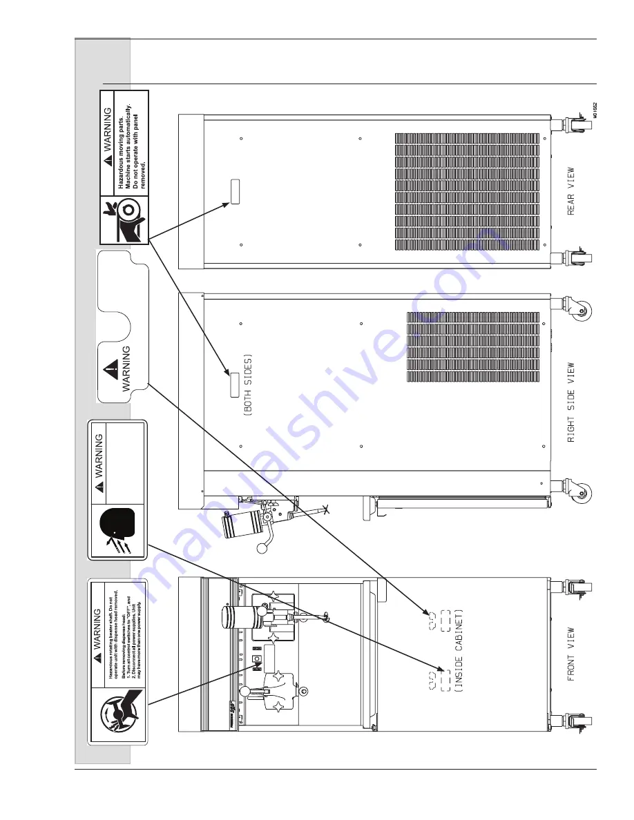
Safety Decal  Locations 

HC165025

1

HC165246

2

HC165048

3

HC165126

4

Pressurized 

system.

Depressurize 

unit

before 

dismantling 

mi

x

transfer 

system.

Do not operate with cover removed!

165048

Содержание Electro-Freeze Genesis Series

Страница 1: ...H C Duke Son LLC P N 185240 April 2015 Printed In U S A OPERATOR S MANUAL with Illustrated Parts List Combination Soft Serve and Shake Freezer Model GEN 2080 185240 4 15...

Страница 2: ......

Страница 3: ...All contents Copyright 2015 H C Duke Son LLC 2116 Eighth Avenue East Moline Illinois 61244 Operator s Manual for Electro Freeze Combination Soft Serve and Shake Freezer Model GEN 2080 i HC185240...

Страница 4: ...or WARNING are typically near specific hazards on the freezer General precautions are listed on CAUTION safety decals In this manual CAUTION messages with the safety alert symbol call attention to saf...

Страница 5: ...his manual to identify the decal and contact your local Electro Freeze Distributor or call or write to H C Duke Son LLC DO NOT attempt to operate the GEN 2080 freezer until you read and understand all...

Страница 6: ...tributor or H C Duke Son LLC When ready to order you will need to determine the 1 part number 2 type of label 3 location of label and 4 quantity required and include a return shipping address Safety D...

Страница 7: ...t Serve Model GEN 2080 185240 vii Safety Decal Locations HC165025 1 HC165246 2 HC165048 3 HC165126 4 Pressurized system Depressurize unit before dismantling mix transfer system Do not operate with cov...

Страница 8: ...ta Plate 5 3 4 Reference Information 5 3 5 Dimensions 6 4 Part Names and Functions Soft Serve 8 5 Part Names and Functions Shake 14 6 Operator Controls 18 7 Operator Display Menu 21 8 Disassembly and...

Страница 9: ...up Instructions Shake 53 13 1 Sanitizing Instructions 54 13 2 Priming 55 14 Closing Procedures 56 14 1 Night Switch Operation 56 14 2 Draining Product 56 15 Product Information 58 15 1 Overrun 58 15...

Страница 10: ......

Страница 11: ...up Therefore it is important to follow the assembly and priming procedures detailed in this manual Make sure all personnel responsible for equipment operation completely read and understand this manua...

Страница 12: ...and notify the carrier s local agent immediately 1 Remove the carton from the pallet and move the machine as close as possible to the permanent location 2 Remove the shipping bolts on the bottom of t...

Страница 13: ...tes independently 2 Check the data plate for fuse size wire ampacity and electrical specifications tied together so that one water inlet and one water waste is all that is required The connections are...

Страница 14: ...y ___________________________________ Address ___________________________________ ___________________________________ Phone ___________________________________ 3 2 Installation Date GEN 2080 Combinati...

Страница 15: ...ence Information Write in Reference Information HERE Fill in this information as soon as you receive the Electro Freeze GEN 2080 Soft Serve Shake Freezer The item numbers encircled correspond with the...

Страница 16: ...ELECTRO FREEZE Soft Serve Model GEN 2080 6 185240 Figure 3 2 3 5 Dimensions W C Water Cooled Models A C Air Cooled Models ACR Air Cooled Remote Models dimensions are the same as W C MODEL GEN 2080...

Страница 17: ...d procedure similarities between the shake and soft serve sides we have separated them to make it easier for you to find the information you need You may notice a duplication of some information Where...

Страница 18: ...5240 4 Part Names and Functions Soft Serve Figure 4 1 Head Assembly HEAD DISPENSE NOZZLE P L U N G E R O R I N G P L U N G E R O R I N G P L U N G E R O R I N G H E A D ROD PLUNGER PLUG AIR BLEED O RI...

Страница 19: ...ecures the handle to the dispense head 6 O RING PLUG Seals the air bleed plug in the dispense head 7 PLUG AIR BLEED Seals the air bleed opening in the head when closed Allows excess air to be removed...

Страница 20: ...ELECTRO FREEZE Soft Serve Model GEN 2080 10 185240 4 Part Names and Functions Soft Serve Figure 4 2 Soft Serve Beater Shaft Assembly...

Страница 21: ...duct 3 BLADE SCRAPER SOFT SERVE Scrapes the frozen product from the freezing cylinder wall Important Soft serve blades only have 2 holes and are not interchangeable with the 3 hole shake blades If the...

Страница 22: ...METER TUBE AIR RETAINER AIR TUBE CLAMP SOFT HOSE HOSE MIX BRAIDED SUPPORT ROLLER BEARING HOSE TRANSFER RED LINE ROLLER ASSY COMPLETE SHOE ROLLER CLAMP SOFT HOSE O RING PORT AIR MIX INLET CLIP TUBE RE...

Страница 23: ...the mix tube in the air mix port 1 SUPPORT ROLLER BEARING Holds roller assembly in place 2 SHOE ROLLER Provides an opening to insert the mix transfer hose Squeezes transfer hose against rollers 3 ROL...

Страница 24: ...ELECTRO FREEZE Soft Serve Model GEN 2080 14 185240 5 Part Names and Functions Shake Figure 5 1 Head Assembly...

Страница 25: ...ASSY PLUNGER SWITCH Starts the freezer when dispensing Must be in place before freezer will operate 8 FUSE SLO BLOW 1A Prevents the spindle motor from overload 9 SPINDLE ASSY FRONT MOUNT Mixes the sh...

Страница 26: ...ELECTRO FREEZE Soft Serve Model GEN 2080 16 185240 5 Part Names and Functions Shake Figure 5 2...

Страница 27: ...tes in the freezing cylinder blending air and mix and ejecting product 3 O RING SHAFT SEAL Seals the beater shaft to the shaft seal Is inserted into the shaft seal washer Must be lubricated 4 WASHER S...

Страница 28: ...in place before the freezer will operate 1 Function Buttons Four Pressing any of these buttons will activate the icon directly above in the display screen Left side L1 L2 Right Side R1 R2 2 OFF Key Wh...

Страница 29: ...intain temperatures in the cylinder and cabinet below 41 F and keep product from deteriorating Use this position when the freezer will not be in use for periods of more than one hour Important Night s...

Страница 30: ...Buttons to move the cursor up or down to the desired sub menu Once the desired menu is highlighted in this example we will use Basic Settings press the select button to enter the sub menu Product Type...

Страница 31: ...look at logged events i e power switch cycle low mix etc The log will display the last 50 events with the newest event at the top Error Log Allows the operator to look at logged errors i e Barrel ref...

Страница 32: ...Shown Freeze Mode Y or N Clean Mode Y or N Standby Mode Y or N Cab Only Mode Y or N Cones Left 5 Screen Settings Operator can turn on or off the following functions Display Cabinet Temperature Y or N...

Страница 33: ...etting LEFT RIGHT OFF OFF Press to start Left Clean Mode Press to start Right Clean Mode CABINET ON 370 F LEFT RIGHT OFF OFF CABINET ON 37 0 F PUMP ON OFF PUMP ON OFF BEATER ON OFF BEATER ON OFF Press...

Страница 34: ...to Section 9 Closing Procedures 9 1 Draining Product 5 Remove the spigot switch rods and open the spigots completely 6 Inside the refrigerated cabinet remove the MTS cover loosen the shoe clamp hand...

Страница 35: ...hose and the air relief opening in the dispense head 4 HC158026 BRUSH 1 inch diameter 12 inches long used to clean the disassembled shaft seal and bushing 5 HC158037 BRUSH 1 4 inch diameter 18 1 2 inc...

Страница 36: ...ure 8 2 Disassemble the Head Assembly 8 2 Disassembly Instructions Soft Serve HEAD DISPENSE NOZZLE P L U N G E R O R I N G P L U N G E R O R I N G P L U N G E R O R I N G H E A D ROD PLUNGER PLUG AIR...

Страница 37: ...om out and down Remove the hand knobs 3 and pull dispensing head 1 straight out by gently rocking the head from the studs 3 Remove the cylinder bushing and beater shaft from the cylinder 4 Remove the...

Страница 38: ...oosen the hand knob c swing back the shoe clamp d swing open the roller shoe e loosen the clamp on braided hose f pull tube off cylinder inlet and slide hose assembly out of roller support housing 12...

Страница 39: ...abel Use warm water 100 to 110 F or 38 to 43 C to wash rinse and sanitize 2 Wash all parts removed from the freezer thoroughly with dish detergent Clean the following parts with the appropriate suppli...

Страница 40: ...itizing the parts must remain fully immersed in the sanitizer for 5 minutes Allow parts to air dry after sanitizing 4 Using a warm mild dish detergent solution thoroughly brush a the mix feed tubes fr...

Страница 41: ...ions for each MTS shoe 1 Remove the O rings and slide the shoe off of the pivot arm and the swing clamp off of the clamp arm See figure 7 12 2 Carry to the sink wash in mild detergent with the brush p...

Страница 42: ...o Section 9 Closing Procedures 9 1 Draining Product 5 Remove the spigot switch rods and open the spigots completely 6 Inside the refrigerated cabinet remove the MTS cover loosen the shoe clamp hand kn...

Страница 43: ...ead and small parts 4 HC158018 BRUSH 7 16 inch diameter 12 inches long used to clean transfer hose braided hose and the air relief opening in the dispense head The following accessories shipped with t...

Страница 44: ...ELECTRO FREEZE Soft Serve Model GEN 2080 34 185240 9 2 Disassembly Instructions Shake Figure 9 2 Shake Head Assembly...

Страница 45: ...ll the head straight out by gently rocking the head from the studs 6 Remove the head bushing 2 and the beater shaft from the cylinder 7 Remove the scraper blades and shaft seal from the beater shaft R...

Страница 46: ...ly from the Mix Transfer System as follows figure 9 5 a remove cover b loosen the hand knob c swing back the shoe clamp d swing open the roller shoe e loosen the clamp on braided hose f pull the braid...

Страница 47: ...air relief plug openings and all O ring grooves as shown in figure 9 7 Figure 9 7 Clean Head Openings and Ports The cleaning instructions explained in this section are procedures to remove bacteria a...

Страница 48: ...t solution thoroughly brush a the mix feed tubes from the cabinet to the cylinders figure 9 10 b the inside of the cylinders making certain to clean the back walls and the inside of the drain tubes as...

Страница 49: ...ions for each MTS shoe 1 Remove the O rings and slide the shoe off of the pivot arm and the swing clamp off of the clamp arm See figure 8 10 2 Carry to the sink wash in mild detergent with the brush p...

Страница 50: ...w any lubricant to come into contact with the bell shaped rubber portion of the seal 3 Install the shaft seal over the rear of the beater shaft with the bell shaped portion facing the rear as shown in...

Страница 51: ...er 9 and insert halfway into the head 1 8 Install and lightly lubricate the 4 inch head O ring 12 9 Position the handle 4 in the head and plunger assembly Lock in place with the handle pin 5 10 Instal...

Страница 52: ...slide a clamp over the hose to secure it to the port Finger tighten only The thumbscrew must lie parallel to the mix air inlet port 14 Slide another clamp over the mix transfer hose and connect to the...

Страница 53: ...ller assembly making sure the locating line is facing out The line should be in the same position at the inlet and outlet guides of the roller bearing support as shown in figure 10 7 21 Swing the shoe...

Страница 54: ...BE CLAMP SOFT HOSE HOSE MIX BRAIDED SUPPORT ROLLER BEARING HOSE TRANSFER RED LINE ROLLER ASSY COMPLETE SHOE ROLLER CLAMP SOFT HOSE O RING PORT AIR MIX INLET CLIP TUBE RETAINER CLAMP SOFT HOSE ARM SWIN...

Страница 55: ...ontact with the bell shaped rubber portion of the seal 3 See figure 11 2 Install the shaft seal over the rear of the beater shaft with the bell shaped portion facing the rear Important Shake blades ha...

Страница 56: ...ke Head Assembly 5 Insert the assembled beater shaft into the cylinder by placing one blade on the bottom of the cylinder and gently pushing This will center the beater and allow alignment with the dr...

Страница 57: ...e slot Failure to install the bushing properly in the dispensing head will damage the beater head and cylinder 10 Install the dispensing head onto the freezer by tilting the top of the head towards yo...

Страница 58: ...he port aligning it with the small locating indent Then slide a clamp over the hose to secure it to the port Finger tighten only The thumbscrew must lie parallel to the mix air inlet port 16 Slide ano...

Страница 59: ...er assembly making sure the locating line is facing out The line should be in the same position at the inlet and outlet guides of the roller bearing support as shown in figure 11 7 23 Swing the shoe o...

Страница 60: ...ELECTRO FREEZE Soft Serve Model GEN 2080 50 185240 Figure 7 8 MTS 11 Assembly Shake continued Figure 11 8 MTS and Mix Tank...

Страница 61: ...the tank covers and low mix probes with sanitizer liquid and the appropriate brush provided 4 Place the mix tank in the refrigerated cabinet Fill with sanitizing solution Important Never let the sanit...

Страница 62: ...e at a time when pure mix is coming out Important Failure to completely remove sanitizer or water from the freezing cylinder before placing in FREEZE will cause the scraper blades to break and damage...

Страница 63: ...erside of the tank covers and low mix probes with sanitizer liquid and the appropriate brush provided 4 Place the mix tank in the refrigerated cabinet Fill with sanitizing solution Important Never let...

Страница 64: ...ortant Failure to completely remove sanitizer or water from the freezing cylinder before placing in FREEZE will cause the scraper blades to break and damage the freezer 12 Allow the MTS to fill the cy...

Страница 65: ...ls with product DO NOT open and close the handle while filing the cup Always keep the spinner blade about on inch in the product 3 When the cup is full close the handle while lowering the cup and remo...

Страница 66: ...sanitized nozzle use a small brush and sanitizer to clean the bottom of the plunger openings continued Figure 14 1 At the end of each day of operation the freezer must be rinsed sanitized and disassem...

Страница 67: ...t the mix pickup tubes into the sanitizing solution 14 Place an empty container under the dispense heads 15 Pull the air bleed plugs up until they touch the bottom of the switch box Open the spigots 1...

Страница 68: ...percentage As mix is frozen in the freezing cylinder air is incorporated into the mix to increase its volume as well as enhance the taste and texture of the finished product The increase in volume is...

Страница 69: ...ong enough to dispense at least one full cylinder of product you will have the overrun that the machine will hold the remainder of the day Contact your mix supplier for the recommended amount of overr...

Страница 70: ...N To prevent bacteria growth remove ALL O rings when cleaning Failure to do so could create a health hazard 2 Clean the cylinder inlet tube drain tube and mix tube with the appro priate brushes 3 When...

Страница 71: ...be necessary to clean mix from the MTS due to hose failure If this happens frequently the MTS should be removed for complete cleaning a Remove cover loosen swing clamp and open shoe to gain access to...

Страница 72: ...shed and the rear drive coupling is rotating and the display does not read HEAD SWITCH Freezer has a head switch or software problem Turn the power switch OFF DO NOT place the freezer in service until...

Страница 73: ...ating properly turn the switches to the OFF position disconnect the main power supply and contact your service technician or the factory DO NOT place the freezer in service until the problem has been...

Страница 74: ...ributor to clean the inside of the freezer including base side panels condenser etc 3 Call your Electro Freeze Distributor to check water cooled condensers and flush clean to remove scale and deposits...

Страница 75: ...d dry all parts thoroughly 3 Store the loose parts such as the head assembly beater assembly and pump parts in a safe dry place 4 Do not lay heavy objects on the plastic or rubber parts 5 Cover the fr...

Страница 76: ...g Tables Caution All maintenance adjustments must be done by an Electro Freeze Distributor or authorized service technician Important Some refrigerants are hazardous to the earth s atmosphere To prote...

Страница 77: ...tro Freeze Distributor for service 7 Faulty selector switch 7 Contact your Electro Freeze Distributor for service 8 Disconnected or broken wire in electrical circuit 8 Contact your Electro Freeze Dist...

Страница 78: ...tch electrically or mechanically stuck closed Unit runs all the time 3 Contact your Electro Freeze Distributor for service 4 Component failure 4 Contact your Electro Freeze Distributor for service 5 L...

Страница 79: ...sembly is not installed 1 Install head assembly 2 Magnetic head switch defective 2 Contact your Electro Freeze Distributor for service 3 Component failure 3 Contact your Electro Freeze Distributor for...

Страница 80: ...stributor for service 2 Cabinet solenoid defective does not open 2 Contact your Electro Freeze Distributor for service 3 Cabinet switch defective 3 Contact your Electro Freeze Distributor for service...

Страница 81: ...le phase only 3 Contact your Electro Freeze Distributor for service 4 High discharge pressure 4 See Discharge pressure too high this section 5 Defective compressor 5 Contact your Electro Freeze Distri...

Страница 82: ...models 5 Contact your Electro Freeze Distributor for service 6 Refrigerant overcharge 6 Contact your Electro Freeze Distributor for service 7 Air in system 7 Contact your Electro Freeze Distributor fo...

Страница 83: ...ontact your Electro Freeze Distributor for service 7 Motor defective or internal overload tripped 7 Contact your Electro Freeze Distributor for service MTS will not shut off 1 Hose broken 1 Replace ho...

Страница 84: ...etween pickup tube and hose 2 Replace as needed 3 Air line hose cracked sucking air 3 Replace air line hose 4 Defective or missing duckbill valve 4 Replace valve Mix shoots out air meter 1 Swing Clamp...

Страница 85: ...ng the test cable does not resolve the issue then the main control board is not functioning properly and needs to be replaced Contact Electro Freeze Factory Tech Support NO Comm The U I Board is not r...

Страница 86: ...g voltage ohm out coil windings If coil is not receiving voltage check relay responsible for activating coil and repair as needed If this condition exists a LOW PSI error code may also trip 5 Check Co...

Страница 87: ...ctions and proper operation and possible voltage drop ohm compressor windings to check for a short and proper winding resistance check compressor starting components for failure allow compressor prote...

Страница 88: ...the unit to ensure it is within specification Check wire connections to the unit and compressor Check compressor contactor for proper operation and possible voltage drop ohm compressor windings to che...

Страница 89: ...Faulty wire connection 4 Program Issue 1 Install Head assembly 2 Test head switch to see if circuit remains open with magnet in place remove and replace head switch as needed 3 Locate Faulty wire conn...

Страница 90: ...ontinues to operate 1 System is Short on refrigerant 2 Solenoid valve not activating 3 Low pressure control is Faulty 4 Restriction is refrigeration system 5 Faulty wire connection 6 System component...

Страница 91: ...ned or changed If this condition is present contact the Electro Freeze Technical Support Line 4 Confirm High pressure control is faulty by installing manifold gages to confirm high side pressure is be...

Страница 92: ...talled 2 Spigot switch has failed in the closed position 3 Spigot Switch is out of adjustment 4 Plunger is sticking open 1 Install Spigot Push Rod and start system to see if error is eliminated 2 Repl...

Страница 93: ...and Pressure relief has not opened check to ensure relief is functioning properly 1 Pump control relay is stuck closed causing pump motor to stay energized 2 Faulty Pressure transducer out of calibra...

Страница 94: ...shorts are present Start unit and check operation 6 Locate and repair faulty wire connections as needed 7 Attempt to calibrate the Transducer to 0 psi and re test unit If unit continues to malfunctio...

Страница 95: ...5 96 VDC then Main P C Board and the communication cable are working properly and the problem lies with the U I Board 4 If 5 96 VDC is read on the black wires but the U I Board does not light up the i...

Страница 96: ...Distributor for instructions prior to warranty compressor replacement Keep your freezer in excellent condition always contact your Electro Freeze Distributor for replacement parts and maintenance sche...

Отзывы: