GDM-397/GDM-461 User Manual
27
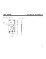
Connect the test leads to the proper terminals as said above to avoid errors. The
LCD will display OL to indicate that the diode being tested is open or that the
polarity is reversed.
The Meter will display the forward voltage drop in voltage
(V) units.
When diode testing has been completed, disconnect the connection between the
testing leads and the circuit under test, and remove the testing leads away from
the input terminals of the Meter.
Содержание GDM-397
Страница 19: ...GDM 397 GDM 461 User Manual 17 B DC AC Current Measurement see figure 3 A GDM 397 A GDM 461 figure 3...
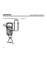
Страница 22: ...MEASUREMENT OPERATION 20 C Resistance Measurement see figure 4 mAuA COM V Hz figure 4...
Страница 25: ...GDM 397 GDM 461 User Manual 23 D Testing for Continuity see figure 5 figure 5...
Страница 27: ...GDM 397 GDM 461 User Manual 25 E Testing Diodes see figure 6 figure 6...
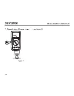
Страница 30: ...MEASUREMENT OPERATION 28 F Capacitance Measurement see figure 7 mAuA V Hz figure 7...
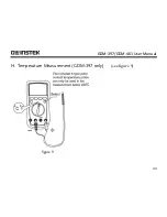
Страница 35: ...GDM 397 GDM 461 User Manual 33 H Temperature Measurement GDM 397 only see figure 9 figure 9...
Страница 62: ...MAINTENANCE 60 Replacing the Fuses figure 13...


