background image

81

GVM-VAC

www.gvm-vac.com

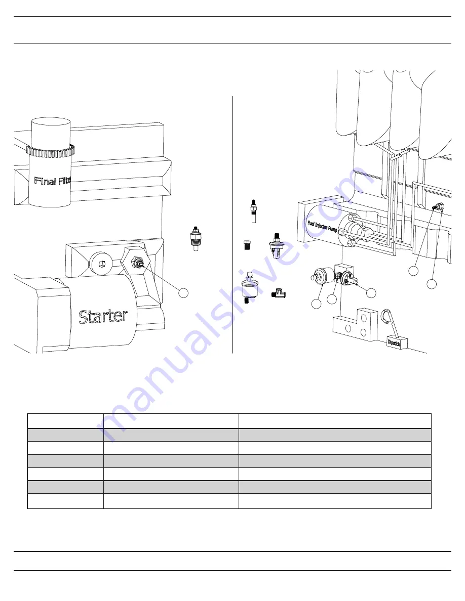
6.8 Engine Senders / Switch Group 

John Deere Engines

ITEM #

PART NUMBER

DESCRIPTION

1.

35423.049

Water Temperature 

Switch

2.

C5104.4.2

Fitting for Water Temperature Switch

3.

9603273

Oil Pressure Switch

4.

1500171

Oil Pressure Sender

5.

3750.2*

Bushing for Oil Pressure Switch and Sender

6.

52320.009

Water Temperature 

Sender

(Facing Radiator)

Left

Right

6

6

4

5

3

1

3

5

1

2

4

2

Содержание GVM8000

Страница 1: ...or Owner s Manual Safety Manual Pre Operating Manual Operating Manual Maintenance Manual Service Manual Parts Catalog Belt Driven Leaf Collector GVM8000 GVM8000 GVM VAC 800 632 7989 www GVM VAC com October 2013 edition 314201 ...

Страница 2: ...PERATE OR REPAIR THE LEAF COLLECTOR WITHOUT FIRST READING AND UNDERSTANDING THIS MANUAL IF YOU HAVE ANY QUESTIONS CONCERNING THE INSTALLATION OR OPERATION OF THIS UNIT PLEASE CALL GVM Vac FOR ASSISTANCE BEFORE ATTEMPTING TO REPAIR OR OPERATE THE UNIT THIS MANUAL IS AN INTEGRAL PART OF THE LEAF COLLECTOR AND SHOULD BE KEPT WITH THE UNIT WHEN IT IS SOLD ...

Страница 3: ... WAY SERIOUS INJURY OR DEATH MAY OCCUR If the decal above is missing or damaged call GVM Vac immediately and we will send you a replacement free of charge Never operate a unit with damaged or missing safety decals GVM Vac s leaf collectors are NEVER to be used to accomodate riders If your unit has been modi fied to accomdate riders remove these modifications immediately as this can result in serio...

Страница 4: ... our product s quality and our customer service Please take the time to thoroughly read this manual as well as the engine manual in its entirety be fore operating maintaining servicing or repairing your leaf collector Please thoroughly review and follow all the safety procedures located in this manual Whenever you need replacement parts service information or any question regarding your GVM Vac pr...

Страница 5: ...er if equipped 32 3 4 Vacuuming Leaves 33 4 0 MAINTENANCE SECTION 4 1 Maintence Overview 35 4 2 Maintenance and Lubrication 36 4 3 Lubrication 37 4 4 Preventative Maintenance 40 4 5 Torque Values 44 5 0 SERVICE SECTION 5 1 Engine Electrical Troubleshooting Guide 48 5 2 Auto Mfg Clutch Adjustment 2008 and after 49 5 3 Hydraulic Boom Troubleshooting Guide 50 5 4 Impeller Installation and Removal 51 ...

Страница 6: ...rts Group 76 6 4 Sheet Metal Group 77 6 5 Engine Mount Group 78 6 6 Muffler Exhaust Assembly 79 6 7 Radiator Assembly Group 80 6 8 Engine Senders Switch Group 81 6 9 Battery Group 82 6 10 Engine Miscelleous Parts Group 83 6 11 Remote Clutch Throttle Circuit Board Assembly 84 6 12 Remote Clutch and Remote Throttle Assembly 85 6 13 Chaffe Eliminator Assembly hinged 86 7 0 CLUTCH GROUP 7 0 87 7 1 Aut...

Страница 7: ...08 10 0 TRAILER GROUP 10 0 109 10 1 Boom Group 110 10 2 Intake Hose Group 111 10 3 M3219 Hydraulic Boom Pump 112 10 4 Curb Nozzle Assembly OPTIONAL 113 MULTI AXIS BOOM SECTION OPTIONAL 11 0 114 11 1 2 or 3X Hydraulic Tank Valve Body Group 115 11 2 2 Axis Boom Assembly 116 11 3 Hinged Boom Frame Assembly 117 INDEX Index 119 TABLE OF CONTENTS Read and understand this entire manual before operating m...

Страница 8: ...entire manual before operating maintain ing or repairing the leaf vacuum 1 0 GENERAL SAFETY 1 0 GENERAL SAFETY Contents 1 0 GENERAL SAFETY 1 1 Safety Symbol Definitions 10 1 2 Do s and Do Not s 11 1 3 Training 13 1 4 Safety Decals 14 1 5 VIN And Serial Number Locations 16 ...

Страница 9: ... WAY SERIOUS INJURY OR DEATH MAY OCCUR If the decal above is missing or damaged call GVM Vac immediately and we will send you a replacement free of charge Never operate a unit with damaged or missing safety decals GVM Vac s leaf collectors are NEVER to be used to accomodate riders If your unit has been modi fied to accomdate riders remove these modifications immediately as this can result in serio...

Страница 10: ...ult in minor or moderate injury or property damage 1 1 Safety Symbol Definitions This manual provides the owners operator with procedures for safe opera tion maintenance and repair of your leaf collector As with any machine there are hazards associated with their operation For this reason safety is emphasized throughout this manual To highlight specific safety information the following safety defi...

Страница 11: ...any alcohol or medi cation 8 DO NOT operate this unit if you have a record of mental instability or dizzi ness which could result in injury to yourself or others 9 DO NOT operate this unit if you are under 18 years of age 10 DO NOT operate this unit without fully inspecting the unit for any damage or leakage 11 DO NOT operate if the unit has any excessive vibration 12 DO NOT operate unit with the ...

Страница 12: ...he leaf collector 2 DO follow engine and PTO manufacturer operating and maintenance instructions 3 DO check fuel lines and fittings frequently for cracks or leaks Replace if necessary 4 DO completely inspect the unit before leaving the service garage 5 DO check the tow tongue each day for cracks 6 DO inspect and be attentive to what is being vacuumed 7 DO check the impeller liners and blower housi...

Страница 13: ...s For this reason it is vital that the owner accept the responsibility to implement a training program that will provide every operator or mechanic the basic skills and knowledge to make good judgement in all situations This training program must include the entire scope of hazards precau tions and government regulations encountered in the vacuuming process The program should stress the need for r...

Страница 14: ...ard Danger Check Impeller and Liners Daily for Wear Danger Inspect Tow Bar for Damage Warning Check Lug nuts GVM Vac leaf collection systems sticker Throttle decal Safety Shut off Ignition decal 1 2 3 4 5 6 7 8 9 10 11 12 13 14 15 16 ITEM NO PART NUMBER DESCRIPTION 200182 200179 200181 200109 200055 200177 200059 200183 200178 200189 200180 200104 200120 200112 LH Side 5 6 7 Inside Pedestal 2 of e...

Страница 15: ...15 GVM VAC www gvm vac com SAFETY PRECAUTIONS 1 2 3 4 5 6 7 8 9 10 11 12 13 14 15 16 1 4 Safety Decals Decal Layout for LCT60C 600 650 6000 ...

Страница 16: ...owable total weight of the fully loaded trailer including liquids cargo and the tongue weight of any towed vehicle the GAWR or Gross Axle Weight Rating which is the maximum al lowable weight the axles are designed to carry The tire inflation pressure is also on the sticker figure 1 5a VIN Number Tag Make sure each operator knows and understands the load ratings of the towed vehicle and that he she...

Страница 17: ...he leaf vacuum 2 0 PRE OPERATING SECTION 2 0 Pre Operating Section 2 0 PRE OPERATING SECTION 2 0 PRE OPERATING SECTION 2 1 Instrument and Controls 18 2 2 Safe Operations 20 2 3 Preparation For Operation 22 2 4 Pre Transport Checks 23 2 5 Personal Protective Equipment and Clothing 25 2 6 Work Site Preparation 26 ...

Страница 18: ...er This gauge indicates the engine r p m s The sender is located on the tachometer The hour meter is digital and indicates the accumulated hours of the engine This should be used to schedule maintenance Volt Meter The gauge shows the status of the engine charging system When the charging system is operating properly it should read approximately 14 volts If the gauge reads below 13 volts the altern...

Страница 19: ...itch Inspection Door Indicator Light Indicates that the limit switch located on the blower housing in spection door has been tripped thus shut off the engine Emergency Stop Switch Indicator Light Indicates that the emergency stop switch on the LCT650 only has been depressed tripping the safety switch and shutting off the engine ROCKER SWITCHES Strobe Light Switch Turns the strobe light on or off R...

Страница 20: ...ed and experienced maintenance and service personnel Operators who qualify to operate this equipment under the above restric tions shall also comply with the following physical requirements 1 Have good vision and the ability to read and understand this manual as well as all safety and operational decals on the equipment 2 Be capable of hearing with or without a hearing aid at a level needed to saf...

Страница 21: ...tor must demonstrate or provide evidence of qualificatation and experience prior to operating the leaf vacuum 4 Each operator must be able to recognize existing or potential problems re garding the mechanical integrity of the leaf vacuum and report any main tenance requirements to the supervisor in charge 5 Each operator must wear the proper personal clothing and safety gear Refer to SAFETY PRECAU...

Страница 22: ...xt three sections should be performed prior to leaving the storage area 1 Check engine fuel coolant and oil levels see EOM 2 Check engine air filter 3 Check all bolts and nuts to ensure they are tight 4 Check all controls for free and proper operation 5 Check main drive belt if equipped for proper adjustment 6 Inspect the fan blades to ensure that they are not bent deformed fatiqued or cracked Rep...

Страница 23: ...eaf vacuum while towing to ensure proper weight distribution The hitch may have to be adjusted when towing with vehicles of varying tow hitch height 2 Safety chains installed correctly 3 Chains routed under trailer tongue in an X pattern between tow vehicle and trailer 4 Slack in chain should be adjusted to permit turning but should not be drag ging on the ground 5 Connect trailer wiring to the to...

Страница 24: ...ravel 9 Check the intake hose boom to verify that it is securely fastened to the leaf vacuum and can not swing free if equipped 10 Verify there are no loose tools or materials on the trailer inside the intake and exhaust hoses or inside the engine sheet metal 11 Check all cones wheel chocks signs or other support tools and materials to ensure proper stowage 2 4 Pre Transport Checks continued ...

Страница 25: ...E EQUIPMENT 1 Head Protection Hard hats without under chin strapping 2 Eye Protection Wraparound goggle type eye protection held in place with an elastic band around the head or a hard hat mounted face shield which provides full protection of the face 3 Eye protection must meet ANSI Z87 1 standards 4 Hearing Protection plug type or muff type ear protection should be worn at all times while operati...

Страница 26: ...ut it is imperative that all leaves be inpsected for obvious dangerous material before vacuuming 2 The operator should never be in the line of traffic the operator should work on the shoulder whenever possible 3 The operators should place cones or other barriers to provide adequate warnings to vehicles and pedestrians that vacuuming is in progress 4 Strobe lights on the leaf vacuum and on the tow ...

Страница 27: ...Read and understand this entire manual before operating maintain ing or repairing the leaf vacuum 3 0 OPERATING SECTION 3 0 OPERATING SECTION 3 1 Starting Engine 28 3 2 Engaging the PTO 30 3 3 Fluid Drive Coupler if equipped 32 3 4 Vacuuming Leaves 33 ...

Страница 28: ...ngine figure 3a Review the Engine Operating Manual supplied with your leaf vacuum for specific start up maintenance and operat ing instructions It is especially important to review break in service procedures for brand new units Starting Procedure refer to figures 3a and 3b 1 Perform all the pre starting pre operating checks out lined in the EOM and in this manual 2 Make sure the PTO is disengaged...

Страница 29: ...el 8 After the engine starts continue to hold the Murphy Switch in until the oil pressure gauge reads at least 15 psi The Murphy shut off switch will not allow the engine to oper ate below this level If the gauge does not rise above 15 psi withing 5 seconds stop the engine and determine the cause Normal operating oil pressure is 50 psi with oil at normal operating temperature 9 Check all gauges fo...

Страница 30: ...efer to figures 3b 3c and 3d 1 Perform all the pre starting pre operating checks outlined in the EOM and in this manual 2 Start the engine as previously discussed in this manual and in the EOM 3 Once the engine has been allowed to thoroughly warm up engine temperature gauge should read at least 180 de grees pull the throttle control until the engine reaches 1000 rpm 4 Grasp the PTO handle fig 3b a...

Страница 31: ...ge the cause DO NOT operate a unit that is in a state of disrepair 6 If the unit is running smoothly and does not dispaly any excessive vibration the unit is ready to vacuum leaves NOTE Please see the next section before vacuuimg leaves Disengaging the PTO refer to figures 3b and 3d 1 Decrease the rpm to 1000 rpm 2 Grasp the PTO handle and slowly disengage the PTO 3 When the PTO is fully disengage...

Страница 32: ... attached and make sure the front of the hose is clear of any objects which could be inadvertently vacu umed at any time Figure 3 3A IMPORTANT If the unit experiences any heavy vibrations or makes any unusual noises shut the engine down and after following the necessary safety guidelines have a qualified technician investigate the cause DO NOT operate a unit that is in a state of disrepair The suc...

Страница 33: ...rlier in this manual 2 Set the engine throttle to around 1400 rpm 3 NOTE Always vacuum leaves using the lowest rpm as possible This saves fuel and decreases the amount of dust escaping the box container 4 Lower the intake hose to a few inches above the leaf pile Hold the intake nozzle at a 45 degree angle to allow proper air flow This should allow the leaves to be vacuumed DO NOT bury the intake n...

Страница 34: ...rstand this entire manual before operating maintain ing or repairing the leaf vacuum 4 0 MAINTENANCE SECTION 4 0 MAINTENANCE SECTION 4 1 Maintence Overview 35 4 2 Maintenance and Lubrication 36 4 3 Lubrication 37 4 4 Preventative Maintenance 40 4 5 Torque Values 44 ...

Страница 35: ...d and understand the Safety Pre operating and Operating sections of this manual before doing any prodcedures in this section A properly maintained leaf vacuum will dramatically extend the life of the unit and will create a safer work place as well For the general safety and welfare of all personnel it is important to create a scheduled maintenance program that covers all the elements in this manua...

Страница 36: ...re Pressure X Inspect Radiator and Radiator Screen X Check Engine as described in Engine s Owner Manual X Inspect Blower Housing Exterior X Check Trailer Lights and Turn Signals X Check Power Band X Inspect Impeller Thoroughly for Damage X Check All Nuts and Bolts for Tightness X Check Tow Bar for Damage Wear X Check Bolt Hole where Tongue Connects to Trailer X Clean and Inspect Battery and Connec...

Страница 37: ...rication of your unit correlates directly to how long your unit will last A properly maintained unit will last much longer than a unit that is not maintained properly NOTE Always lubricate bearings at the end of each work day This will displace any moisture in the bearings Also lubricate thor ougly before extended shutdown or storage Lubrication Points 1 Drive Bearings figure 4 3a These bearings a...

Страница 38: ... the grease cap hole The trailer wheel bearings should be checked and greased after the first 30 days of service then at the beginning of every season Grease specifications Thickener Point Lithium Complex Dropping Point 230 degr C minimum Consistency NLGI No 2 Additives EP Corrosion Oxidation Inhibitors Base Oil Solvent refined Petroleum Oil Base Oil Viscosity 40 deg C 150cSt Min Viscosity Index 8...

Страница 39: ... bearing grease fitting These bearings are sealed and do not require greasing The PTO crossover shaft and linkage should be lubricat ed with high temperature lithium base 2 lubricant after 200 hours of operation 5 Hinge and Friction Points Leaf vacuum operation and longevity can be improved by keeping hinges and friction points lubricated It is recommended that lubricaton be performed weekly Use S...

Страница 40: ...ase consult the manufacturer before doing any preventative maintenance procedures not specifically mentioned in this manual Proper preventative maintenance of your unit just like lubrication correlates directly to how long your unit will last A properly maintained unit will last much longer than a unit that is not maintained properly Preventative Maintenance 1 Engine Oil Change the oil and oil fil...

Страница 41: ...t condition and coolant mix ratio as well as cool ant conditioners are all critical to proper engine cooling See the engines owner s manual for specifics on coolant mixture ratios and conditioners The radiator should be inspected and cleaned with compressed air everyday at the very least 4 Engine Air Cleaner Due to the large amounts of dust generated in collec tion leaves it is critical to your en...

Страница 42: ...anual for these procedures The brakes should be adjusted after the first 200 miles of operation when the brake shoes and drums have seated and at 3 000 mile intervals or as use and performance requires The adjustment procedures are beyond the scope of this manual please see the axle owners service manual for specific instructions The trailer brakes should be inspected and serviced at yearly interv...

Страница 43: ...er tension If the belt shows any sign of cracking it should be replaced immediately The proper tension of the belt should be approximately 1 2 deflection when applying a 8 pound pull 10 FASTENERS Fasteners should be checked weekly for the first 30 days and monthly thereafter They must be in place at all times and properly torqued For general torque values see the torque chart at the end of this se...

Страница 44: ...150 1500 1 1 4 950 1200 1500 1950 M30 950 1200 1350 1700 1600 2000 1 3 8 1250 1550 2000 2550 M33 1300 1650 1850 2350 2150 2750 1 1 2 1650 2100 2650 3350 M36 1650 2100 2350 3000 2750 3500 Lub means coated with a lubricant such as engine oil or fasteners with phospate or oil coatings Dry means plain or zinc plated without any lubrication DO NOT use these values if a different torque value or tighten...

Страница 45: ...TEMPT TO OPERATE OR REPAIR THE LEAF COLLECTOR WITHOUT FIRST READING AND UNDERSTANDING THIS MANUAL IF YOU HAVE ANY QUESTIONS CONCERNING THE INSTALLATION OR OPERATION OF THIS UNIT PLEASE CALL GVM Vac FOR ASSISTANCE BEFORE ATTEMPTING TO REPAIR OR OPERATE THE UNIT THIS MANUAL IS AN INTEGRAL PART OF THE LEAF COLLECTOR AND SHOULD BE KEPT WITH THE UNIT WHEN IT IS SOLD ...

Страница 46: ...THE 5 0 SERVICE SECTION Service and Troubleshooting Wiring Diagrams SERVICE SECTION www gvm vac com GVM Vac ...

Страница 47: ...2008 and after 49 5 3 Hydraulic Boom Troubleshooting Guide 50 5 4 Impeller Installation and Removal 51 5 4 Impeller Installation and Removal continued 52 5 5 Belt Adjustment and Replacement Guide 53 5 6 Flange Bearing Installation and Removal 54 5 7 Impeller Installation and Removal 55 5 8 Replacing the Blower Housing Liners 56 5 8 Replacing the Blower Housing Liners continued 57 ...

Страница 48: ...rent If there is no current at B power is not getting to the shut off switch Then the problem is not the shut off switch 8 If there is current at terminal B put a test light on the fuse at location Z Fig 3 If there is no current there the fuse is blown Replace fuse 9 If there is current at B and Z push the override button letter X Fig 3 in on the shut off switch While the button is depressed place...

Страница 49: ... adjustment the gauge should slide between the nut and rocker ball with a slight amount of pressure See PIC 4 Move the adjustment nut to create the 1 8 gap Re install the return spring Place the handle in the disengaged position Check to make sure that the PTO output shaft turns freely 1 2 3 4 5 6 7 Rotating Shafts pulleys and moving belts can cause severe injury or can be fatal The engine and dri...

Страница 50: ...otor part MP 08004 but the solenoid is bad and needs to be replaced Sole noid part number is MP 17744 4 If there is NO current at the post item 1 check the wiring between the switch and the solenoid If the wiring checks out okay the switch is bad and needs to be replaced BOOM WILL NOT GO DOWN 1 Using a test light make sure there is current at the outside solenoid post item 2 this has a 4 gauge Red...

Страница 51: ...Fig 5 This will separate the bushing from the impeller Alternate from one bolt to the other driving only about a 1 4 at a time to keep the bushing coming out straight It is imperative to keep the bushing straight to remove it IMPORTANT Be sure to drive the bushing out evenly or it will get in a bind making removal much harder 6 If the bushing does not come off using the two bolts drill and tap sev...

Страница 52: ...n contact with the impeller 5 Tap the bushing onto the shaft aligning the keyways 6 BELT DRIVE UNITS Align the bushing and key to be flush with the end of the shaft Fig 1 7 DIRECT DRIVE UNITS The bushing and key should pro trude from the shaft about 1 2 inch Fig 2 8 Put the 3 bolts into the non threaded holes and drive them into the impeller holes evenly Alternate between the three bolts as you dr...

Страница 53: ... tor assembly Move the motor assembly approximately two inches then do the same to the other side Continue alternating between the two sides until the belt is tight 3 IMPORTANT Use a straight edge to make sure the pulleys are aligned figure 4 4 If the pulleys are not aligned use either of the adjustable motor mount nuts to compensate for the mis alignments Check the tightness at the center of the ...

Страница 54: ...pulley side 5 5 8 Figure 2 Now slide the concentric collar toward the respective bearing making sure the grooved side is toward the bearing Turn the concentric collar clockwise until it slips over the inner ring extension and engages the eccentric Turn by hand until the parts are locket together Place a punch or drift in the blind hole in the collar and strike it sharply to lock the collar and rin...

Страница 55: ...eed to be ordered that has a larger diameter hole Units manufactured before April 2002 will most likely need to be converted to the new bearing plate part number LCT600 603 all but LCT6000 and LCT630 104A for the LCT6000 This plate is for the blower housing or impeller side only The pulley side bearing does not use the steel debris collar Completely tighten the two Allen head screws See figure 6 N...

Страница 56: ...aining welds to free the liners DO NOT remove the stop piece at the bottom of the housing TO INSTALL Place the short liner into lip at the rear of the housing and line up the bottom of the liner with the stop at the bottom of the housing The short liner has the overlap piece on it and should be installed as shown in the pictures at the left Tack weld the liner in place every 8 to 10 inches to help...

Страница 57: ... the overlap piece Make sure the liner slips under the rear lip and the overlap piece Tack weld the long liner to the overlap piece and tack weld around the liner as you did on the short liner Install the two bolt in liners just as they were removed Installing the Liners refer to 5 5a and 5 5b contin ued 3 4 5 Make sure the negative battery cable is discon nected before opening the blower housing ...

Страница 58: ...ed 61 5 10 4 Engine Wiring Harness Descriptions 62 5 10 4 Engine Wiring Harness Descriptions continued 63 5 10 5 Engine Rocker Switch Wiring Diagrams 64 5 10 5 Main Circuit Board 65 5 10 6 Main Circuit Board Plug Diagrams 66 5 10 7 Trailer Plug Wiring Diagram 67 5 10 8 Trailer Wiring Diagram 68 5 10 9 Brake Wiring Harness 69 5 10 10 Boom Wiring Diagram 70 5 10 11 Remote Throttle Clutch Wiring Harn...

Страница 59: ...g pages 2 Engine Wiring Harness Diagram Aux Engine Harness June 2005 and after Note The number in parentheses is the pin number the wire goes to If there are two numbers the first number is the pin for the main harness while the second number is the pin number of the smaller harness 5 10 1 Engine Wiring Diagram ...

Страница 60: ...60 GVM VAC www gvm vac com Service Section Engine Main Harness 5 10 2 Engine Main Harness Enlarged ...

Страница 61: ...ux Engine Harness Note Not all wires will be installed in the small harnesses If the unit wasn t ordered with the factory installed option then the wiring to that option may not be included in the harness 5 10 3 Auxillary Engine Harness Enlarged ...

Страница 62: ...rness pin 7 Throttle Slow goes to Remote Clutch Harnss pin 8 Strobe Light goes to Strobe Light Harness pin 1 Strobe Light Aux goes to Strobe Light Harness pin 3 Aux from Ignition goes to Aux Plug Harness pin 1 from Solenoid Battery Aux from Igntion goes to Aux Plug Harness pin 3 Red 10 gauge Yellow Yellow Yellow w Orange Stripe Orange w Yellow Stripe Yellow w Green Stripe EMPTY Green w Yellow Stri...

Страница 63: ... from Ignition came from Aux Engine Harness pin 16 from Ignition came from ground on Solenoid from ignition came form Aux Engine Harness pin 2 from ignition came from ground on solenoid Rocker Switch came from Aux Engine Harness pin 5 Rocker Switch came from Aux Engine Harness Yellow Black Yellow w Green Stripe Green w Yellow Stripe EMPTY EMPTY Yellow w Blue Stripe Blue w Yellow Stripe EMPTY Yello...

Страница 64: ...Yellow Yellow w Green Stripe Black Black Yellow Black Yellow Throttle Fast Clutch Engage from Circuit Board Throttle Slow Clutch Disengage from Circuit Board Looped from 9 Looped from 10 Looped from 5 Looped from 2 Pin Color Description Caterpillar Engine Heater Rocker Switch 1 2 3 4 5 6 7 8 9 10 Orange w Yellow Stripe Yellow Yellow w Orange Stripe Yellow Black Orange w Yellow Stripe Black Yellow ...

Страница 65: ...low Red Yellow Red Yellow Red Rem Throttle Shutdown Indicator Lights Oil Temp Trp Door E Stop unfused Battery Red Black from ignition Yellow 14 15 16 17 18 19 20 21 Relay Aux Plug Wire ID s 14 Eng Heat Yellow Orange 15 Eng Heat Aux Orange Yellow 16 Clutch Engage Yellow Green 17 Clutch Disengage Green Yel 18 Throttle Fast Yellow Blue 19 Throttle Slow Blue Yellow 20 Strobe Light Yellow Purple 21 Aux...

Страница 66: ...ig 14 Empty 15 Empty 16 Empty Pin Description 1 Red from battery 2 Yellow Aux Plug harness 3 Yellow Remote Throttle Har 4 Yellow Orange stripe Aux har 5 Orange Yellow stripe Aux har 6 Yellow Green stripe Clutch Eng 7 Empty 8 Green Yellow stripe Clutch Diseng 9 Yellow Blue stripe Throttle Fast 10 Empty 11 Blue Yellow stripe Throttle Slow 12 Yellow Blue stripe Strobe 13 Purple Yellow stripe Strobe S...

Страница 67: ...67 GVM VAC www gvm vac com Service Section 5 10 7 Trailer Plug Wiring Diagram ...

Страница 68: ...68 GVM VAC www gvm vac com Service Section 5 10 8 Trailer Wiring Diagram ...

Страница 69: ...69 GVM VAC www gvm vac com Service Section 5 10 9 Brake Wiring Harness ...

Страница 70: ...am COLOR FUNCTION Green Down White Up Purple Ground on Solenoid Red 4 gauge cable Positive to Battery Black 4 gauge cable Ground from Solenoid to Hydraulic Motor Black from up down switch changes to Yellow Positive for Boom Rocker Switch on instrument panel if equipped ...

Страница 71: ...71 GVM VAC www gvm vac com Service Section 5 10 11 Remote Throttle Clutch Wiring Harness ...

Страница 72: ...800 632 7989 GVM Vac www gvm vac com PARTS BREAKDOWNS SECTION PARTS BREAKDOWN SECTION 6 0 ENGINE GROUP 7 0 CLUTCH GROUP 8 0 BLOWER HOUSING GROUP 9 0 TRAILER GROUP 10 0 TRAILER GROUP ...

Страница 73: ... Group 76 6 4 Sheet Metal Group 77 6 5 Engine Mount Group 78 6 6 Muffler Exhaust Assembly 79 6 7 Radiator Assembly Group 80 6 8 Engine Senders Switch Group 81 6 9 Battery Group 82 6 10 Engine Miscelleous Parts Group 83 6 11 Remote Clutch Throttle Circuit Board Assembly 84 6 12 Remote Clutch and Remote Throttle Assembly 85 6 13 Chaffe Eliminator Assembly hinged 86 6 0 ...

Страница 74: ...witch ITEM PART NO DESCRIPTION 15 63524 Tachometer Hour Meter 16 62540 Temperature Gauge 17 62542 Oil Pressure Gauge 18 62551 59414 Fuel Gauge if equipped Blank Gauge 19 62555 Volt Meter 20 4045 0021B1 Rocker Switch Safety Light 21 4045 0021A1 Rocker Switch Rem Thrttle 22 4045 0025A Rocker Switch Rem PTO 23 3054 0028 Rocker Switch Engine Heat 24 STD 2003 Switch Harness Light 25 STD 2004 Switch Har...

Страница 75: ...IPTION 1 UU G080023 Air Cleaner Assembly 2 P18105 4 Filter Element 3 P003951 Clamp 4 P102980 Rubber Baffle 5 P103113 Dust Cap 6 P101870 Wing Nut 7 STD 2704 Rubber Elbow 8 P004307 Mounting Bands to sheet metal 9 H001249 Pre Cleaner 10 P020648 Bowl Cover 11 P020227 Bowl 10 11 8 2 6 3 5 9 1 7 4 ...

Страница 76: ...m 6 3 Strobe Light Parts Group ITEM PART NUMBER DESCRIPTION 1 STD 2213 LED Strobe Light 2 60700 Grommett 3 4045 0021B1 Rocker Switch 4 4045 0024B Switch Wiring Harness 5 STD 2214 Wiring Harness rocker switch to light 4 3 5 2 1 ...

Страница 77: ...s Door 6 4045 2101 Front Panel 7 4045 0018 Radiator Screen 8 LCT650 114 Radiator Screen Clamp 9 4045 2109 Panel Door LH ITEM PART NO DESCRIPTION 10 4045 2106A Upper Side Panel LH 11 4045 2112C 4045 2112T Rear Panel NOT SCL Rear Panel SCL 12 4045 2105A Upper Side Panel RH 13 4045 2108 Panel Door RH 14 LCT60 624 Lift and Turn Latch 15 LCT609 602 Overcenter Latch 16 4045 2112F Cover Solenoid 17 STD 6...

Страница 78: ...ON 1 4045 2151A Engine Mount Front 2 4045 2152 Engine Mount Rear 3 4045 2154 Side Rail LH except LCT650 4 4045 2153 Side Rail RH 5 LCT604 603 1 Engine Adjuster Nut 6 LCT604 603 2 Engine Adjuster Bracket 7 LCT604 603 2 Adjustable Motor Mount 8 LCT604 603 B Engine Base Adjuster 9 4045 2155 Wiring Harness Bracket LCT650 rail ...

Страница 79: ...79 GVM VAC www gvm vac com 6 6 Muffler Exhaust Assembly LCT s only with John Deere engines not SCL s May 2004 and after ITEM PART NUMBER DESCRIPTION 1 650 2701 Muffler 2 STD 2702 Clamp muffler 1 2 ...

Страница 80: ...Fan 5 R128443 Fan Spacer 6 G8M8X090 Spacer Bolts 4 required 7 81331 Upper Radiator Hose ITEM PART NO DESCRIPTION 8 C 89C 022 5010 Radiator Cap 9 4045 9681 Lower Radiator Hose 10 4045 2151E Radiator Shim 11 H9601 Radiator Grommet 12 4045 2151F Radiator Bolt Bracket 13 ZSB 500 750 Shoulder Bolt 1 2 3 7 8 10 10 9 4 7 12 12 12 11 11 11 11 11 11 12 12 12 11 11 11 11 11 11 6 6 6 6 13 13 13 13 13 13 13 1...

Страница 81: ...DESCRIPTION 1 35423 049 Water Temperature Switch 2 C5104 4 2 Fitting for Water Temperature Switch 3 9603273 Oil Pressure Switch 4 1500171 Oil Pressure Sender 5 3750 2 Bushing for Oil Pressure Switch and Sender 6 52320 009 Water Temperature Sender Facing Radiator Left Right 6 6 4 5 3 1 3 5 1 2 4 2 ...

Страница 82: ...CT60C 650 42 long LCT600 84B Positive Battery Cable Battery to Solenoid LCT600 6000 84 long 7 LCT60 15B Negative Battery Cable all 15 long 8 BTC R Terminal Cover Red all 9 BTC Terminal Cover Black all 10 LCT600 72SS MET 60SS LCT60C 153SS Red Cable to Hydraulic Boom Pump SCL 600 6000 72 long Red Cable to Hydraulic Boom Pump LCT650 60 long Red Cable to Hydraulic Boom Pump LCT60C 153 long 11 LCT600 2...

Страница 83: ... Group John Deere Engines ITEM PART NUMBER DESCRIPTION 1 39011 2 Throttle Connector 2 4045 9101 Throttle Cable Bracket LCT 3 4045T 9101A Throttle Cable Clamp 4 400016 Fuel Line Bracket 5 2856 26012 Grommet Door 6 ST40 Starter Solenoid 6 5 4 1 3 2 1 2 4 6 5 3 ...

Страница 84: ...TION STD 3000 Entire Assembly 1 only available as an assembly Box and Cover 2 only available as an assembly Backing Plate 3 only available as an assembly Spacer rquires 4 4 only available as an assembly Circuit Board 5 only available as an assembly Actuator Wiring Harness 6 only available as an assembly Instrument Panel and Nozzle Wiring Harness 1 4 3 2 1 5 6 ...

Страница 85: ...or clutch 8 STD 6553 STD 6553B Throttle Cable direct drive Throttle Cable belt drive 9 STD 6557 Throttle Acutator bottom 10 STD 6558 Cable Adaptor throttle 11 STD 6552A Cover ITEM PART NO DESCRIPTION 12 4045 6565 Throttle Cable Bracket 13 4045 6564 Clutch Cable Bracket 14 STD 6563 Torque Coupling 15 STD 6562 Coupling Sleeve 16 STD 6560 PTO Cable Adaptor 17 STD 6561 Roller Bearing 18 STD 6568 Space...

Страница 86: ...y 2002 must order RAS 102A 4 RAS 105 Shaft 5 RAS 106 Mesh Screen 6 RAS 107 Screen Holder 7 RAS 108 Flange Bearing ITEM PART NO DESCRIPTION 8 RAS 101 Fan 9 RAS 109 Strip Brush 10 RAS 110 Brush Holder 11 RAS 111 Air Deflector 12 RAS 112 Hinge 13 RAS 113 Shaft Bracket 14 LCT609 602 LCT650 114 Over center Latch all but LCT650 Destaco Latch not shown LCT650 only 15 RAS 114 Angle Frame LCT650 only 2 11 ...

Страница 87: ...1 AutoHD PTO Clutch Group 88 7 2 AutoHD PTO Assembly Group 89 7 3 AutoHD PTO Linkage Group 90 7 4 Clutch Assist Group 91 7 5 Kraft Fluid Drive Group Optional 92 7 6 Kraft Fluid Drive Installation Optional 93 7 7 Kraft Fluid Drive Breakdown Optional 94 7 8 Kraft Fluid Drive Common Parts Optional 95 ...

Страница 88: ...d Clutch Assembly 03 08 1 OD 41500217 Pilot Bearing JD 2 OD 41500237 Clutch Disk 3 OD 361919 Pressure Plate 03 08 4 OD 41500248 Throw out Bearing 03 08 5 OD 41500172 Clutch Cover 6 OD 45000054 Bolt 3 18 16 x 1 7 OD 45000063 Lock Washer 3 8 8 OD 45000226 Bolt M10 1 50 x 35MM 9 OD 45000046 Lock Washer M10 10 OD 41500216 Decal Diesel Clutch ...

Страница 89: ...sembly items 1 11 13 OD 48080050 8OF Complete PTO Clutch Assembly 1 OD 45000212 Bolt 5 16 18 x 1 1 4 HD model 2 OD 41500205M Bearing Retainer Cover 3 OD 41500206 PTO Bearing Rear 4 OD LCT650 601K OD LCT650 601F Key Stepdown direct drive units only Key belt drive units only 5 OD 41500203 PTO shaft 6 OD 45000105 Bolt 9 16 12 x 1 3 4 7 OD 45000177 Bolt 9 16 12 x 3 8 OD 45000103 Lock Washer 9 16 9 OD ...

Страница 90: ... 6 41500019 Linkage Rod End 7 see below Shaft Lever 8 41500102 Shaft Housing AutoHD 9 41500043 Grease Zerk 10 NLA NLA ITEM PART NO DESCRIPTION 11 41500045 Shaft Bushing 12 41500046 Shaft Collar 13 41500030 Rocker Ball 14 45000050 Nut 3 8 16 15 41500072 Pivot Ball 03 08 16 45000177 Bolt 3 8 16 x 1 3 4 17 45000063 Lock Washer 3 8 18 45000064 Flat Washer 3 8 19 45000012 Bolt 1 4 28 x 2 20 45000015 Lo...

Страница 91: ... PART NUMBER DESCRIPTION 1 400050 A Clutch Cylinder 2 400054 C Cylinder Support Bracket JD 3 41500095 Clutch Bracket Arm Auto HD 4 41500019 Linkage Rod end 41500019A Linkage Threaded insert 5 400050 C1 Bearing 6 41500102 Pivot Shaft Tube Auto HD 7 41500041A HD Pivot Shaft 8 400050 C2 Spacer ...

Страница 92: ...92 GVM VAC www gvm vac com 7 5 Kraft Fluid Drive Group Optional Fluid Drive Coupler Optional ...

Страница 93: ...93 GVM VAC www gvm vac com 7 6 Kraft Fluid Drive Installation Optional Fluid Drive Coupler Optional ...

Страница 94: ...94 GVM VAC www gvm vac com 7 7 Kraft Fluid Drive Breakdown Optional Fluid Drive Coupler Optional ...

Страница 95: ... Optional Fluid Drive Coupler Optional ITEM PART NUMBER DESCRIPTION 1 UU TFP7018CC 390 Degree Fuse Plug 5 8 2 UU TFP2292 Seal Kit 3 UU 8202AD Roller Bearing 4 UU TFP103602X Shaft 5 UU 8002DX Bearing small 6 UU 8002AS Ball Bearing 7 UU KPC2 01 5 Fluid 1 1 2 gallon ...

Страница 96: ... com 8 0 BLOWER HOUSING GROUP BLOWER HOUSING GROUP 8 0 8 0 BLOWER HOUSING GROUP 8 0 96 8 1 Blower Housing Group 97 8 2 Blower Housing Face Group LCT600 98 8 3 Belt Drive Assembly 99 8 4 Pedestal Group 100 8 5 Exhaust Duct Assembly 101 ...

Страница 97: ...CT620 601 Blower Housing Back 2 LCT620 602 Liner Set 3 LCT600 603 Inner Bearing Plate 4 LCT620 602A Bolt In Wrap Around Liner 5 LCT620 603 Flat Head Bolt 6 LCT620 603N Nut 7 LCT600 33 Impeller 8 LCT650 601 Impeller Bushing 9 LCT650 601F Bushing Key 10 LCT600 615 Shaft Protector 11 5CZ 500 750 Shaft Bolt 12 LCT620 604 Liner Straight 13 LCT620 602 D Spacer ...

Страница 98: ... DESCRIPTION 1 LCT621 601FB1 Blower Housing Face 2 LCT616 604 Intake Flange 3 LCT600 635 1 Lock Rod 4 STD 4000 Limit Switch Box 5 STD 4001 Limit Switch Actuator 6 SCL621 602 Inspection Door 7 6410 51 Limit Switch 8 600 2431C Limit Switch Harness 9 LCT616 801 Boom Bearing 10 LCT621 603 Inspection Door Hinge ...

Страница 99: ...650 606 K Driver Belt 6 LCT650 603A Sheave Pulley 7 LCT650 604A Bushing 8 LCT611 612 Belt Guard Inside Cover ITEM PART NO DESCRIPTION 9 LCT650 601F Bushing Key 10 LCT611 622 Belt Guard Mount 11 LCT600 611 Outer Bearing Plate 12 LCT650 601K Step Down Key not 6000 13 LCT910 100 Rake Rack 14 2875 Grommet for Rake Rack 15 6410 51 Limit Switch 3 3 2 2 1 4 4 5 9 12 7 7 6 6 8 4 10 3 15 3 4 14 13 14 14 14...

Страница 100: ...09 602 Overcenter Latch 3 LCT650 602 A Flange Bearing 2 1 4 4 LCT600 611 Outer Bearing Plate 5 600 2213 Pedestal Utility Door 6 600 2214 Hinge 7 LCT622 602 L Latch 8 LCT614 601 Pedstal Lid 9 LCT650 0 Shaft 10 LCT650 602 C Lock Collar for Bearing 11 LCT650 602 D Spacer 12 6410 51 Limit Switch 1 2 2 9 4 6 7 5 12 8 11 10 10 3 3 ...

Страница 101: ... www gvm vac com 8 5 Exhaust Duct Assembly LCT600 after February 2001 ITEM PART NUMBER DESCRIPTION 1 LCT621 610 Discharge Duct 2 LCT621 611B Transition 61 3 LCT616 616 Hose Band 4 LC MDH 16 48 Exhaust Hose 1 2 3 4 ...

Страница 102: ... vac com 9 0 TRAILER GROUP TRAILER GROUP 9 0 9 0 TRAILER GROUP 9 0 102 9 1 Trailer Bed Group 103 9 2 Fuel Tank Group 104 9 3 Tongue Group 105 9 4 Hydraulic Parking Jack OPTIONAL 106 9 5 Axle Hub Assembly 107 9 6 Brake Assembly 108 ...

Страница 103: ... Bed 600 LCT633 630 01 Trailer Bed 6000 7 LCT622 614TE Axle Assembly 600 6000 11 Axle Assembly 6000 ITEM PART NO DESCRIPTION 8 STD 2414 Tail Light Assembly 9 OD 60250R LED Light only 10 OD 60700 Grommett 11 OD 94706 Plug Harness 12 STD 2201 LED Market Light Yellow 13 STD 2201G Grommett marker light 14 STD 2202 LED Marker Light Red 15 600 2437 License Plate Mount Brkt 16 LCT600 010 License Plate Br...

Страница 104: ...2521 Fuel Cap 3 600 2525 Fuel Sender 4 MET633 901 Fuel Fitting not for pickup 5 MET633 901M Fuel Fitting Grommett 6 600 2527 Fuel Fitting pickup tube and screen 7 600 2526 Tee Fitting 8 600 2523 Side Support Bracket 9 600 2522 Center Support Bracket 10 400016 Fuel Line Bracket mounts on engine rail 1 7 7 8 2 4 4 4 5 5 5 5 6 3 ...

Страница 105: ...l 4 200012 Pintle Eye Pins 5 200009 Safety Hook 3 8 6 LCT600 201 Safety Chain 7 LCT622 626 Power Cord 13 incl ITEM PART NO DESCRIPTION 8 LCT622 633 LCT622 634 LCT622 636 Tow Bar LCT60C 650 Tow Bar LCT600 Tow Bar LCT6000 9 LCT622 624 Parking Jack 12 LCT622 635A LCT622 635B Hose Lock Brkt 600 Hose Lock Brkt 6000 13 89102 Breakaway Switch included in 7 8 13 6 5 9 12 12 10 11 7 4 4 4 3 2 1 ...

Страница 106: ...TD 9008 Clamp Top 10 STD 9007 6000 9007 Clamp Bottom 600 800 650 Clamp Bottom 6000 ITEM PART NO DESCRIPTION 11 5CZ 500 1 5 Clamp Bolts 12 80 1550 Hydraulic Pump 13 80 1552 Fitting 90 degree 14 80 1552 Fitting 90 degree 15 STD 9009 STD 9009B Hydraulic Hose Top Hydraulic Hose Top 2 3X 16 STD 9010 STD 9010B Hydraulic Hose Bottom Hydraulic Hose Bttm 2 3x 17 STD 9012 Battery Cable Red 18 STD 9013 Batte...

Страница 107: ... Bearing Cup 4 31 32 1 Outer Bearing Cup 5 31 32 2 Outer Cone 6 006 001 00 Spindle Nut 7 N A N A 8A 021 042 01 Grease Cap 8B 085 001 00 Rubber Plug 9 005 023 00 Spindle Washer 10 7 122 Wheel Stud 1 2 20 11 005 101 00 Tang Washer 12 006 080 00 Lug Nut 1 2 20 20 K23 105 K23 106 Electric Brake Assembly LH Electric Brake Assembly RH 24 008 201 05 Grease Hub and Drum ...

Страница 108: ...0 Actuator Lever Arm Assembly LH Actuator Lever Arm Assembly RH 3 027 005 00 Wire Clip 4 046 009 00 Retractor Spring 5 K71 048 00 Shoe and Lining Kit 6 043 004 00 Adjuster Assembly 7 046 0118 00 Adjusting Screw Spring 8 K71 105 00 042 099 01 027 099 00 046 080 00 Magnet Kit containing 1 Magnet 1 Magnet Clip 1 Magnet Spring 9 046 007 00 Plug 10 046 016 00 Wire Grommet 11 005 004 00 Lockwasher 12 00...

Страница 109: ... GVM Vac www gvm vac com 10 0 HOSE BOOM GROUP 10 0 TRAILER GROUP 10 0 TRAILER GROUP 10 0 109 10 1 Boom Group 110 10 2 Intake Hose Group 111 10 3 M3219 Hydraulic Boom Pump 112 10 4 Curb Nozzle Assembly OPTIONAL 113 ...

Страница 110: ...6 611B SS Button Hold Down 8 STD 2322 Push Button Box 9 LCT616 615D Hold Down Bracket 10 STD 2320E Cover Plate ITEM PART NO DESCRIPTION 11 ZENC 625 Nut 12 LCT616 607 Hose Support Hanger 13 5CZ 625 4 0 Bolt 14 600 2322B Boom Harness 15 RMB531 Bushing 16 9405 4 4 90 Degree Fiting 17 LCT617 608 Hydraulic Hose 18 3219 PC Boom Pump Cover 19 200022 Pump Spacer 20 M3219 S Boom Pump 21 9205 4 4 Straight F...

Страница 111: ...120 LC SDH 16 120 UC LC MDH 16 100 Intake Hose except SCL Intake Hose Urethane multi axis Intake Hose SCL800 2 LCT616 601 Intake Nozzle 3 LCT616 616 Hose Band Bolt Style 4 LCT616 603U LCT616 603U B Hose Clamp 3 8 thick hoses Hose Clamp urethane hoses 5 LCT616 607 Hose Support Tube 1 3 3 4 2 5 ...

Страница 112: ...BER DESCRIPTION MP M3219 S Complete Pump Assembly all above 1 MP 08004 Electric Motor 12V 2 MP 17744 Solenoid Switch heavy duty 3 MP 19283 D Coil Cartridge Assembly 4 MP 07193 D Cartridge 5 MP 10861 D Coil 2 way 2 position 6 MP 06232 Plastic Reservoir 3 5 x 15 7 2 1 6 5 4 3 ...

Страница 113: ...CT686 211106 LCT679 LCT680 LCT677 LCT677A LCT687 211107 LCT665 LCT616 611A LCT675 001 Bumper Deflector Shield Lock Rod for Shield Destaco Clamp for above Adjustment Bar Adjustment Spring Adjustment Threaded Rod Roller Bearing 1 75 Roller Bearing 1 Clevis Pin 1 Gasket Safety Cover Clamp Set Collar for Hinge Pin Limit Switch Brass bushing for hinge pin Hinge Pin Spacer tube for hinge pin 16 17 18 19...

Страница 114: ...AL Multi Axis Boom Section OPTION 800 632 7989 GVM Vac 11 0 MULTI AXIS BOOM SECTION OPTIONAL 11 0 114 11 1 2 or 3X Hydraulic Tank Valve Body Group 115 11 2 2 Axis Boom Assembly 116 11 3 Hinged Boom Frame Assembly 117 INDEX Index 119 ...

Страница 115: ...ydraulic Tank Valve Body Group 1 2 3 4 5 6 7 8 9 10 LCT600 6000 multi axis units January 2006 and after Hydraulic Hose 1 2 Hydraulic Hose 1 2 Hydraulic Pump double valve Hyd Pump single valve 90 Degree Fitting Wiring Harnss to Valve Body Wiring Harness to Joystick Fitting to Tank Joystick Assembly single Joystick Assembly dual Hose Hose STD 9015 650 142 Varies Varies 800 950 800 900 ITEM NO PART N...

Страница 116: ... Boom 600 6000 multi axis units January 2006 and after 7 5 4 1 3 2 6 ITEM PART NUMBER DESCRIPTION 1 800 903 Joystick 2 Box Cover 3 Box 4 800 952 Box Bottom comes with 5 5 800 952 Box Holder comes with 4 6 800 953 Grip Fitting strain relief 7 Wiring Harness ...

Страница 117: ... when using 90 degree nozzle Boom Arm 2 axis when using standard nozzle 3 SCL816 812 Boom Cylinder 4 800 704B Auburn Gear 5 800 701D Hydraulic Motor 6 Call Chain 7 LCT622 635 Boom Hanger Bracket 8 LCT616 601 90MA 90 Degree Nozzle ITEM PART NO DESCRIPTION 9 LCT616 616 Hose Clamp 10 LCT616 603U Hose Support 11 Varies please call Intake Hose 12 800 708 Bolt 3 4 16 x 4 5 Long 13 800 710 Bolt 3 4 16 x ...

Страница 118: ...812 Cylinder Up Down 7 800 704B Auburn Gear 8 800 701D Hydraulic Motor 9 SCL816 813 SCL816 813 24 Hose Support Tube 18 Hose Support Tube 24 10 Call Chain 11 LCT616 601 A HD Nozzle 45 degree 12 LCT616 603U Hose Support Band 13 SDH 16 120 UC Intake Hose 10 Long PART NO DESCRIPTION 14 LCT616 616 Hose Clamp 15 800 708 Bolt 3 4 16 x 4 5 Long 16 HYF 1028 Fitting 90 degree swivel 17 800 712 Nut 3 4 18 80...

Страница 119: ...2005 and after 5 4 3 2 7 8 1 6 ITEM PART NUMBER DESCRIPTION 1 800 600C Boom Frame 2 SCL816 501 Bearing 3 800 707A Boom Mast Knuckle 4 800 704B Auburn Gear see breakdown next page 5 800 801D Hydraulic Motor 6 800 609 Frame Support 7 SCL816 503L Boom Stop LH 8 SCL816 503R Boom Stop RH ...

Страница 120: ...4 01 102 12 Bearing Cup 5 Hex Head Bolt grade 8 6 Flat Washer 7 03 04 101 09 Pipe Plug 8 Hub 9 04 01 101 17 Bearing Cone 10 14 02 410 003 Retaining Ring Kit 11 Ring Gear ITEM PART DESCRIPTION 12 Carrier Assembly 13 Sun Gear 14 Thrust Washer 15 Cover 16 14 00 052 002 Magnetic Plug 17 Hex Head Bolt 18 03 04 101 01 Pipe Plug 641008 Bearing and Seal Kit includes 2 3 4 8 and 10 641017 Seal Kit includes...

Страница 121: ...Y WAY SERIOUS INJURY OR DEATH MAY OCCUR If the decal above is missing or damaged call GVM Vac immediately and we will send you a replacement free of charge Never operate a unit with damaged or missing safety decals GVM Vac s leaf collectors are NEVER to be used to accomodate riders If your unit has been modi fied to accomdate riders remove these modifications immediately as this can result in seri...

Страница 122: ... 108 Cylinder Hydraulic Multi Axis 111 D Deflector Shield Curb Nozzle 108 Discharge Duct 96 Disk Clutch 87 Door Inspection 93 Drum 102 Dust Cap 74 E Engine Adjuster Nut 77 Engine Base Adjuste 77 Engine Moun 77 Exhaust Manifold 78 F Fan Chaffe 85 Fender 98 Filler Cap 110 Filter Element 74 Filter Hydraulic 110 Flange Bearing 85 Fork 89 Frame 112 Front Panel 76 Fuel Cap 99 Fuel Fitting 99 Fuel Gauge ...

Страница 123: ...tch Safety Light 73 Roller Bearing 84 108 Rubber Plug 102 S Sender Oil Pressure 80 Water Temperature 80 Shaft 95 Shaft Bushing PTO 89 Shaft Collar PTO 89 Shaft Lever 89 Shaft Protector 92 Shaft PTO 88 Sheave 94 Shroud 79 Side Panel 76 Side Rail 77 Site Gauge 110 Spacer Bearing 92 95 Spindle Nut 102 Spindle Washer 102 Sprocket 111 Starter Solenoid 82 Step down Key 94 Striker Plate 94 Strip Brush 85...

Страница 124: ...TEMPT TO OPERATE OR REPAIR THE LEAF COLLECTOR WITHOUT FIRST READING AND UNDERSTANDING THIS MANUAL IF YOU HAVE ANY QUESTIONS CONCERNING THE INSTALLATION OR OPERATION OF THIS UNIT PLEASE CALL GVM Vac FOR ASSISTANCE BEFORE ATTEMPTING TO REPAIR OR OPERATE THE UNIT THIS MANUAL IS AN INTEGRAL PART OF THE LEAF COLLECTOR AND SHOULD BE KEPT WITH THE UNIT WHEN IT IS SOLD ...

Отзывы: