background image

54

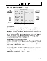
IDE Data Port Write

Selecting Enabled speeds up processing of drive reads and writes, but may cause
instability in IDE subsystems that cannot support such fast performance. If you are
experiencing disk driver errors, try setting this value to Disabled. This field does not
appear when the Internal PCI/IDE field, above, is Disabled.

IDE HDD Block Mode

Block mode is also called block transfer, multiple commands, or multiple sector
read/write. If your IDE hard drive supports block mode (most new drives do), select
Enabled for automatic detection of the optimal number of block read/writes per sector
the drive can support.

Onboard FDC Controller

Select 

Enabled 

if your system has a floppy disk controller (FDC) installed on the system

board and you wish to use it. If you install an add-in FDC or the system has no floppy
drive, select 

Disabled

 in this field.

Onboard Serial Port 1/2

Select an address and corresponding interrupt for the first and second serial ports.

Serial Port 2 IRDA

Select 

Enabled 

if your system has a Ir module installed on the system and you wish to

use it.

Onboard Parallel Port

Select a logical LPT port name and matching address for the physical parallel (printer)
port.

Onboard Parallel Mode

Select an operating mode for the onboard parallel (printer) port. Select 

Normal 

unless

your hardware and software require one of the other modes offered in this field.

SPP

Standard parallel port mode (Default)

EPP

Bi-directional mode

ECP

Fast, buffered

ECP+EPP

Bi-directional and buffered

Содержание SL5598

Страница 1: ...Advanced Pentium Motherboard SL5598 USER S MANUAL Copyright 1998 GVC CORPORATION ALL RIGHTS RESERVED...

Страница 2: ...arks of Intel Corporation IBM and OS 2 are registered trademarks of International Business Machines AWARD is a registered trademark of American Megatrends Inc Winbond is a registered trademark of Winb...

Страница 3: ...to which it relates to satisfy all the provisions of the 1994 Regulations FCC Compliance FCC stands for Federal Communications Commission This product complies with FCC Rules Part 15 and has been test...

Страница 4: ...the CPU by correctly aligning the CPU with the Socket7 as noted in the motherboard diagram Once aligned press down on the CPU gently but firmly and lock it into place Install either the 3 3 volt unbuf...

Страница 5: ...EASY INSTALLATION...

Страница 6: ...d Connectors Page 15 3 2 CPU Page 16 3 2 1 Install CPU 3 2 2 Arrange Jumper Settings 3 2 3 Other Jumper Settings 3 3 System Memory DRAM Page 21 3 3 1 SIMM and DIMM 3 3 2 Installation Procedure 3 3 3 M...

Страница 7: ...Menu Page 39 4 4 BIOS Features Setup Menu Page 43 4 5 Chipset Features Setup Menu Page 46 4 6 Power Management Setup Menu Page 47 4 7 PNP PCI Configuration Setup Menu Page 50 4 8 Integrated Periphera...

Страница 8: ...Y INSTALLATION page Each step refers to another section within this manual where you will find more detailed information if needed Check Your Device Items The standard package will contain the followi...

Страница 9: ...2 FEATURES Photo Of The Motherboard...

Страница 10: ...SDRAM 1M 2M 4M 8M 16M 32M bit deep by n bit wide DRAMs and both single and double sided Access Time 70ns or faster for FPM EDO or 60ns or faster for SDRAM Chipset SiS5598 Pentium PCI ISA Chipset Integ...

Страница 11: ...IOS Type AWARD Software Inc 2MB Flash BIOS Hard Disk Driver IDE Auto configuring Plug Play Support Steerable DMA Channels and Interrupts ISA Plug Play Special Features Windows 95 ready Multi Boot PCI...

Страница 12: ...869A Winbond W83781D MIDI Audio Feature Conn CD IN Riser Connector IDE Secondary IDE Primary ES692 SIMM1 SIMM2 SIMM3 SIMM4 DIMM1 DIMM2 Clock Gen JP7 JP8 JP9 JP10 JP11 JP12 JP15 JP16 JP17 RTC Battery C...

Страница 13: ...ard and mouse connectors Page 30 USB connectors Page 30 Two serials ports Page 30 One parallel port Page 30 One VGA port Page 30 Expansion Slots Sockets Socket7 CPU Slot Page 16 SIMM DIMM Sockets Page...

Страница 14: ...onent side up Immediately inspect the board for damage Due to shifting during shipping it is suggested that the installer press down on the entire socket ICs to ensure they are properly seated Do this...

Страница 15: ...ctors Slots Connectors List J1 DIMM2 J2 USB J3 WOL Optional J4 DIMM1 J5 SIMM4 J6 Floppy Connector J7 SIMM3 J8 PS 2 Keyboard J9 Power Connector Standard J10 ATX Power Connector Optional J11 SIMM2 J12 P...

Страница 16: ...e install CPU to socket firmly and arrange jumper settings carefully according to Section 3 2 1 and 3 2 2 C 3 2 1 Install CPU The following steps install your CPU and configure the types voltage and s...

Страница 17: ...sink fan will further cool the CPU 3 2 2 Arrange Jumper Setting Because different CPUs may require a varied configuration of Clock CPU BUS speed I O voltage and Core voltage please refer to the follow...

Страница 18: ...CPU I O Voltage Setting CPU Clock CPU TYPE I O Voltage JP14 JP13 CPU Clock MHz JP3 WS2 JP2 WS1 JP1 WS0 P54C K5 6X86 50 P55C K6 6X86L M2 55 60 PIN 1 66 Setting CPU BUS Speed Intel CPU BUS JP17 BF0 JP16...

Страница 19: ...3 INSTALLATION X2 0 X2 5 X3 0 X4 0 Setting CPU Core Voltage Vcore JP8 JP9 JP10 JP11 JP12 2 2V 2 8V 2 9V 3 2V 3 38V 3 52V...

Страница 20: ...this jumper is open for normal operation for other kind of processors VGA Selection JP4 SL5598 also has a 3 pin jumper allows you to enable or disable onboard VGA function Clear CMOS JP7 If an unknow...

Страница 21: ...the SIMM socket same to the DIMM Step2 Insert SIMM module into SIMM socket at a 45 degree angle Push it ahead to 90 degree angle until it locks firmly into the SIMM socket Insert the DIMM module into...

Страница 22: ...s module can only be inserted into DIMM socket one way Please note the s s for pin 1 location To release the memory module push both latches down and carefully rock the module forward and backward whi...

Страница 23: ...48MB 16MBx2 8MBx2 64MB 16MBx2 16MBx2 96MB 16MBx2 32MBx2 72MB 32MBx2 4MBx2 80MB 32MBx2 8MBx2 96MB 32MBx2 16MBx2 128MB 32MBx2 32MBx2 128MB 64MBx2 None 256MB 64MBx2 64MBx2 Note 1 The memory module must b...

Страница 24: ...TY 256MB 128MB 128MB The SL5598 mainboard features two 168 pin DIMM sockets with each supporting 8MB to 128MB of SDRAM EDO using 1MBx64 2MBx64 4MBx64 and 8MBx64 DIMM Asymmetrical single and double sid...

Страница 25: ...nd expansion cards installed The ISA interface also provides byte swap logic and I O recovery support ISA Bus Speed Dividing the PCI clock by 3 or 4 generates the ISA system clock The division by 3 se...

Страница 26: ...to the Host Bridge and CPU The arbitration scheme which we design is done at two layers CPU has the highest priority i e CPU will be the PCI bus owner if there is a request from the Host Bridge If the...

Страница 27: ...ve mode as indicated in the device s manual 3 5 2 Secondary IDE Connector J16 39 pin block This connector supports two secondary channel IDE devices as well as the 120MB Floppy drives via a ribbon cab...

Страница 28: ...ivers and inputs on the drive interface WARNING When you connect a ribbon cable to this port you must orient the cable connector so that the PIN 1 edge of the cable is at the PIN 1 end of the onboard...

Страница 29: ...may or may not support the ATX case mounted Power Switch it is optional which in turn supports System Suspend function When the BIOS sets the Power Button function to Delay 4 sec the system can be set...

Страница 30: ...ch must be a momentary SPST type that is normally open HDD LED Connector 4 pin The SL5598 supports one straight 4 pin header for connecting to front Panel Hard Disk activity LED indicator Infrared IrD...

Страница 31: ...port Parallel Port Printer The SL5598 includes a parallel port EPP ECP compatible The parallel port is capable of being disabled or remapped to either the secondary LPT address or the primary LPT add...

Страница 32: ...case to cool down your system components If your chassis has a Chassis Fan this header will support it CPU Fan Your Pentium Cartridge may have an attached heatsink and Fan which would utilize this co...

Страница 33: ...will allow a shared frame buffer interface to maximize Multimedia performance The feature connector will use pass through signals from a video add in card to utilize the system s VGA circuitry The SL...

Страница 34: ...cord into an outlet of power supply Connect monitor signal cable to system VGA port and the monitor power cord to power outlet 6 Turn on monitor and system power Once Powered on the power LED on the f...

Страница 35: ...3 INSTALLATION...

Страница 36: ...OS Setup 4 1 How To Enter BIOS Setup The AWARD BIOS is immediately activated when you first turn on the computer The BIOS reads system configuration information in CMOS RAM and begins the process of c...

Страница 37: ...ve all the CMOS changes only for Main Menu 4 1 2 Getting Help Press F1 to pop up a small help window that describes the appropriate keys to use and the possible selections for the highlighted item To...

Страница 38: ...the screen ROM PCI ISA BIOS 2A5IIG5D CMOS SETUP UTILITY A W A R D S O F T W A R E I N C S T A N D A R D C M O S S E T U P BIOS FEATURES SETUP CHIPSET FEATURES SETUP P O W E R M A N A G E M E N T S E T...

Страница 39: ...d on the integrated peripherals controller in your system Supervisor User Password Setting Change set or disable a password In BIOS versions that allow separate user and supervisor passwords only the...

Страница 40: ...ng or type the desired value into the field Hard Disks The BIOS supports up to four IDE drives This section does not show information about other IDE devices such as a CD ROM drive or other hard drive...

Страница 41: ...of heads write precompensation factor landing zone and number of sectors Drives whose specifications do not accommodate any pre defined type are classified as type USER Size Disk drive capacity approx...

Страница 42: ...s Adapter Video Graphics Array For EGA VGA SEGA SVGA or PGA monitor adapters CGA 40 Color Graphics Adapter power up in 40 column mode CGA 80 Color Graphics Adapter power up in 80 column mode MONO Mono...

Страница 43: ...Memory Base Memory is typically 640 KB It is also referred to as conventional memory The DOS operating system and conventional applications utilize this type of memory Extended Memory Extended Memory...

Страница 44: ...ta from the main DRAM into cache memory for even faster access by the CPU The External Cache field may not appear if your system does not have external cache memory Boot Sequence The original IBM PCs...

Страница 45: ...te Setting When Disabled the following two items Typematic Rate and Typematic Delay are irrelevant Keystrokes repeat at a rate determined by the keyboard controller in your system When Enabled you can...

Страница 46: ...proves the performance of the system BIOS and similar ROM firmware for expansion peripherals but it also reduces the amount of high memory 640 KB to 1 MB available for loading device drivers etc Enabl...

Страница 47: ...this area of system memory usually discusses their memory requirements VGA Shared Memory Size You can share the system memory in this item for VGA use VGA Memory Clock MHz Set the Memory speed Linear...

Страница 48: ...CI ISA BIOS 2A5IIG5D POWER MANAGEMENT SETUP AWARD SOFTWARE INC Esc Quit Select Item F1 Help PU PD Modify F5 Old value Shift F2 Color F7 Load Setup Defaults Move to items Exit to Main Menu Modify value...

Страница 49: ...ards Association VESA Use the software supplied for your video subsystem to select video power management values Blank Screen System only writes blanks to the video buffer Switch Function This allows...

Страница 50: ...curring at a COM serial port will awaken a system which has been powered down MODEM use LPT Ports Activity When set to Enabled any event occurring at a LPT printer port will awaken a system which has...

Страница 51: ...hannel The IDE standard supports two channels interfaces with two devices on each Enable the second channel if your system has two PCI IDE connectors in use either on the system board or on expansion...

Страница 52: ...rrupts INT A INT B INT C and INT D By default a PCI connection is assigned INT A Assigning INT B has no meaning unless the peripheral device requires two interrupt services rather than just one Becaus...

Страница 53: ...IDE Burst Mode Selecting Enabled reduces latency between each drive read write cycle but may cause instability in IDE subsystems that cannot support such fast performance If you are experiencing disk...

Страница 54: ...ct Enabled if your system has a floppy disk controller FDC installed on the system board and you wish to use it If you install an add in FDC or the system has no floppy drive select Disabled in this f...

Страница 55: ...ion Select Enabled if your system contains a PS 2 port and you have a PS 2 mouse in use USB Controller This allows you to enable USB Bus or not USB Keyboard Support Select Enabled if your system conta...

Страница 56: ...password each time the system boots and whenever you enter Setup Setup Enter a password whenever you enter Setup NOTE To clear the password simply press Enter when asked to enter a password Then the...

Страница 57: ...bers of the cylinders are less than or equal to 1024 no LARGE option will be show Users can select a mode which is appropriate for them 4 13 Save Exit Setup This feature allows the changes to be made...

Отзывы: