3. INSTALLATION
3.5.5 Front Panel connectors (J27) and IrDA Connector (J23)
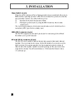
Front Panel includes headers for the following eight I/O connectors:
Power LED, Keyboard Lock, Speaker, Power Switch(optional), Reset, Sleep,
HDD LED and 4sec Power switch(Optional).
Power LED (3-pin)
Can be connected to a LED that will light when the computer is powered on.
Keyboard Lock (2-pin)
Allows you to lock your keyboard with a button or a key manually.
Speaker Connector (4-pin)
It is used to drive a chassis-mounted speaker if desired.
Power Switch & 4 sec Power Switch( Optional, 2-pin & 2-pin)
This connector may or may not support the ATX case-mounted Power Switch, it
is optional, which in turn supports System Suspend function. When the BIOS sets
the Power Button function to “Delay 4 sec.”, the system can be set to the
suspended mode once you push the power switch for no longer then 4 seconds. If
the power switch is pushed down for over 4 seconds the system will be totally
Power Off. When the BIOS setting sets the Delay 4 second to “Instant-off”, then
Power Switch function work as regular power switch.
Reset Switch Connector (2-pin)
Supports the front panel case-mounted reset button. It is advised that the reset
switch be used for rebooting the system in order to extend the life of the system’s
power supply.
Pwr SW
Reset
Sleep
H D D L E D
4sec Pwr SW
Pwr LED
K/B Lock
Speaker
IrDA
C
Содержание SL5598
Страница 1: ...Advanced Pentium Motherboard SL5598 USER S MANUAL Copyright 1998 GVC CORPORATION ALL RIGHTS RESERVED...
Страница 5: ...EASY INSTALLATION...
Страница 9: ...2 FEATURES Photo Of The Motherboard...
Страница 35: ...3 INSTALLATION...


