


24
BEVEL OPERATION
1. Before performing a bevel, always check the following:
a. The machine has been set-up in accordance with the previous section of this
manual, entitled “Bevel Settings” (I.e. correct bevel angle settings; initial Slide Base
setting; machine height adjustment; and correct Guide Roller adjustment).
b. IMPORTANT: The Main Roller and two Support Rollers must run free and
smooth.
c. IMPORTANT: The Slide Base must be seated correctly, with no contamination
between it and the Pivot Arm Block, and the Slide Base Bolt must be firmly
tightened.
d. IMPORTANT: The cutter nut must be firmly tightened and the cutter teeth must
be in good condition.
2. Raise the Clamp Rollers so that the clearance between the Clamp Rollers and the Main
Roller is greater than the thickness of the plate to be bevelled.
3. Place the material, or an off-cut of the material, on the Main and Support Rollers.
4. Then screw the fluted handle, clockwise until the clamp rollers have pinched the material.
Note: The clamp rollers should not be screwed down too tightly on the plate
material. This will cause feeding difficulties. The material should be able to move
freely under the clamp rollers.
5. Remove the material.
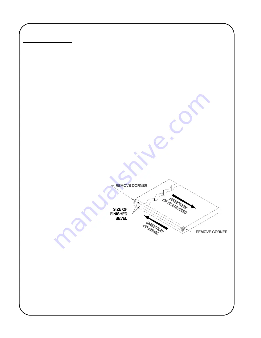
6. It is recommended that the
corners of the leading and
trailing edges of the plate
material be ground prior to
bevelling. The notched
corners should be at least the
depth of the final bevel depth.
This procedure will reduce the
initial and the final stresses
applied to the cutter and will
improve the initial grip of the material for feeding.
7. Connect electrical power, release the Emergency Stop Mushroom button (if latched) and
start the cutter rotation by pressing the start (“
I”
) push button.
Check for correct cutter
rotation!
8. Feed the machine/material straight in and out. Try to minimize the external forces applied to
the cutter. Avoid applying twisting forces to the machine or plate. Do not shake the
machine or twist the plate when the cutter is engaged with the plate. Do not attempt to
readjust the machine settings such as root face or Guide Roller alignment during bevelling
operations. Always stop the machine and disengage from the material before adjustment of
these settings.
Содержание KBM-18
Страница 2: ......
Страница 8: ...4 KBM 18 080 UNDERCARRIAGE ...
Страница 23: ...19 22 5º 30º 22 5º BEVEL ARRANGEMENT 30º BEVEL ARRANGEMENT ...
Страница 24: ...20 37 5º 45º 37 5º BEVEL ARRANGEMENT 45º BEVEL ARRANGEMENT ...
Страница 25: ...21 55º 55º BEVEL ARRANGEMENT ROOT FACE SCALE EXAMPLES ...
Страница 42: ...38 KBM 18 100 GENERAL ASSEMBLY BREAKDOWN Drawing Number KBM 18 100 ...
Страница 43: ...39 KBM 18 100 GENERAL ASSEMBLY BREAKDOWN Drawing Number KBM 18 100 ...
Страница 45: ...41 PIVOT ARM ASSEMBLY BREAKDOWN Part Number KBM 18 213 ...
Страница 46: ...42 SLIDE BASE ASSEMBLY BREAKDOWN Part Number KBM 18 212 ...
Страница 49: ...45 STARTER ASSEMBLY BREAKDOWN Drawing Number KBM 18 214 ...
Страница 50: ...46 MANUAL STARTER ASSEMBLY BREAKDOWN Drawing Number KBM 18 215 1 2 3 ...
Страница 54: ...50 OPTIONAL HYDRAULIC UNDERCARRIAGE ASSEMBLY BREAKDOWN Part Number KBM 18 080 ...
Страница 55: ...51 OPTIONAL HYDRAULIC UNDERCARRIAGE ASSEMBLY BREAKDOWN Part Number KBM 18 080 ...
Страница 56: ...52 OPTIONAL UNDERCARRIAGE ASSEMBLY BREAKDOWN Part Number KBM 18 069 ...
Страница 57: ...53 KBM 18 WIRING SCHEMATIC Drawing Number KBM 18 215 SCH ...
Страница 60: ...www GULLCO com ...