Author: Alain Thurner
Created: 12/11/2009
Process owner: Martin Knuchel
Released: 16.03.2018 / Version 34
Page 1 of 3
Risikobeurteilung_EN_V34.xlsx
M
inor
M
oder
at
e
S
ev
er
e
Ra
re
Ofte
n
F
requent
A
B
C
D
E
F
G
H
I
J
K
L
M
1
4
10
1
2
3
The following should be
prevented:
1.1
x x x x x x x x x x x x x x
x
x
Processing of hazardous
materials. Fire and danger of
explosion.
Thermal factors
All
Non-compliance with the intended
use
Someone is injured or killed
x x
10 3/d Someone is injured or killed
Intended use: Güdel devices are only used to bring objects to a specific position,
hold them there or move them simultaneously with other machine movements.
No hazardous (e.g. poisonous or explosive) objects must be moved. Güdel devices
must not be operated in potentially explosive areas. The ambient temperature
during operation must be between 5° and 40 °C.
If the intended use is modified, this can result in hazards that are
not covered by the safety concept.
x Y
1.2
x
x x x
x x x x
x
x
Suspended load
Technician,
forwarding
agent,
commissioning
technician
Faulty lashing of slings, improper
use, defective or insufficient hoists
Injuring or killing of persons due to
components falling down
x x
10 3/d Persons are injured or killed by
falling parts.
Use appropriate lifting equipment. Wear protective clothing. Keep a safe distance.
Observe the operating manual. Never step below suspended loads
None
x Y
1.3
x
x x x
x x x x
x
x
Heavy load
Technician,
forwarding
Lifting without auxiliary agents,
falling
Physical injuries
x x
10 3/d Persons are injured
Use suitable lifting units. Use trained personnel as well as protective clothing
None
x Y
1.4
x
x
x
Movement of the axes
Setters
Unexpected start
Someone is surprised by the
unexpected situation and injured as a
result
x x
10 3/d When the enable button is
pressed, the operator is
exposed to a hazard due to an
automatic movement triggered
by a third party.
Axes can only be moved individually by a two-hand operating device in jog mode.
In the event of several carriages on a single gantry, the individual carriages have
to be selected using a key switch. The enable button is a "shock button".
For the enable button to be activated, only one safety door may be open and the
others must be closed and confirmed. Safety-relevant parts of the control are
inspected at appropriate time intervals by the machine control system.
In confirmation mode, the operator must pay great attention and
have a high level of individual responsibility. Only perform
movements if no other person is in the danger area and none of
your own body parts are in the line of danger of the
corresponding axis.
x Y
1.5
x
x
x
x
Movement of the axes,
suspended loads
(vertical axes and
workpieces)
Operator,
maintenance
personnel,
commissioning
technician
Gripper problems
Defective motor brake
General problems in the drive train
Someone is surprised by vertical
movement and injured as a result.
x
x
20 3/d That neither operating
personnel nor third parties can
reach or walk into the
hazardous locations where
automatic movements are
performed. The areas of
movement must be secured
accordingly.
The areas of movement are enclosed by light grids, light curtains as well as
mechanical safety fences so that it is impossible to enter this area from any
direction.
There are door elements or light barriers that allow access to the danger area or to
a portion of the danger area.
The height of the safety fences is described in EN ISO 13857.
Safety shutdown situation:
The vacuum system remains active in a de-energized state.
Door elements: When opening the danger area, a safety shutdown is performed for
at least those drives that pose a hazard in this area.
The door elements are also locked electromechanically.
Light barriers: These are monitored so that when contact is broken, at least those
drives that pose a hazard in this area are shutdown. The distance between the
source of the danger and the light barriers is described in EN ISO 13855.
In normal operation, all protective hoods must be closed.
Removable protective hoods must be screwed securely.
Required behavior:
Inspect the protective hoods before starting normal operation.
Safety shutdown situation: Never step into the area below
suspended workpieces and vertical axes.
x Y
1.6
x x
x
Movement of the axes,
suspended loads
(vertical axes and
workpieces)
Technician,
forwarding
agent
Removal of transport securing
device without supporting
suspended loads and axes.
Someone is surprised by the
unexpected movement and injured as
a result
x x
10 3/d Suspended loads fall.
Before removing the transport securing device, support the suspended loads or
axis.
If motors or gearboxes are removed, vertical axes must always be secured or
supported.
None
x Y
1.7
x x x x
x
x
Movement of the axes.
Parts are flung out
Operator,
maintenance
personnel,
cleaning
personnel
Unexpected start
Someone is surprised by the
unexpected situation and injured as a
result
x x
10 3/d A person is injured by the
unexpected start-up of moving
parts.
The start-up of the plant without the enable button being pressed or available must
be prevented.
With the permission device pressed, moving plant parts can be moved in a
controlled manner, even if the plant is unsecured.
When the enable button is pressed, it must not be possible for the operator to be
endangered by an automatic movement triggered by a third party.
The lockable main plant switch breaks all main and control circuits.
Never step into the area below suspended workpieces and vertical
axes.
In confirmation mode, the operator must pay great attention and
have a high level of individual responsibility.
If motors or gearboxes are removed, vertical axes must always be
secured or supported.
x Y
1.8
x
x
x
Parts flung out
Setter,
third parties
Gripper problems, defective motor
brake, torn belt (telescopic axis),
pressure drop (load balancing),
general problems in the drive train
Someone is surprised by parts flying
off and injured as a result.
x x
10 3/d Parts are flung out.
The axes can only be moved with reduced speed.
Rotating parts must be shut down securely.
Work in this mode requires great attention and a high level of
individual responsibility from the operator. Only perform
movements if no other person is in the danger area and none of
your own body parts are in the line of danger of the
corresponding axis.
x Y
1.9
x
x
x
Parts flung out
Operator,
third parties
Parts clamped improperly
Breakage of rotating tools
Someone is surprised by parts flying
off and injured as a result.
x x
10 3/d Operating personnel or third
parties are injured by parts that
become loose and fly away.
Mechanical guards must be placed in the possible flight path of parts that could fly
away.
Safety devices are inspected by means of calculation and trial.
In normal operation, all protective hoods must be closed,
removable protective hoods must be screwed securely.
Required conduct: Inspect the protective hoods before starting
normal operation.
x Y
1.10 x
x x x x
x
x
Parts flung out
Operator,
third parties
Carrier hits mech. buffer unit.
Moving parts are torn out of their
holder and hurled away due to the
delay which occurs.
Someone is surprised by parts flying
away and injured as a result.
x x
10 3/d Operating personnel or third
parties are injured by parts that
become loose and fly away.
Attachments to moved masses (vertical and horizontal axes) must be fastened in
such a manner to prevent them from being separated or sheared off due to the
delay. The max. delay must be calculated. The calculation of the fastening and
loading of the attachments must also be taken into account in the construction.
Workplaces and operating devices in the direction of travel
should be avoided as far as possible.
x Y
1.11
x
x
Suspended loads
(vertical axes, telescope
axes, counter balance
cylinders, and workpieces)
Setters
Gripper problems, defective motor
brake, torn belt (telescopic axis),
pressure drop (load balancing),
general problems in the drive train
Person is surprised by unexpected
situation and injured as a result.
x x
10 3/d It must be ensured that when
the enable button is not
pressed, no persons can be
endangered by falling vertical
axes, telescope axes or
workpieces.
Grippers must remain in the de-energized state in clamping position.
To minimize risk, vertical axes can be redundantly equipped with an additional
brake.
Telescope axes and counter balances: Special attention is required here. The axis
(for a telescope axis, the 2nd stage) is to be secured with a mechanism. Operation
in setup mode only when the restricted area is closed off.
Do not walk under suspended workpieces or vertical axes. Take
special care with telescope axes. Inspect belts visually for cracks
and tears before every setup procedure.
x Y
1.12
x
x
Suspended loads
(vertical axes, telescope
axes, counter balance
cylinders, and workpieces)
Setters
Inattention and/or careless
operation by operator
Someone is surprised by the
unexpected situation and injured as a
result
x x
10 3/d Workpieces are dropped
accidentally
Grippers can only be operated in the storage position.
Do not walk under suspended workpieces or vertical axes. Take
special care with telescope axes. Inspect belts visually for cracks
and tears before every setup procedure.
x Y
F
loor
-m
ount
ed dr
iv
e ax
is
R
ai
sed dr
iv
e ax
es
Recommendation to avoid residual risks
Hazard analysis / risk analysis
Machine type: all modules with/without control system
A
ffec
ted per
son(
s)
C
or
res
pondi
ng oper
at
ing
m
ode
Triggering factor
Event
(worst case)
(without protective measures)
S
et
up /
C
hangeov
er
C
leani
ng
T
roubl
es
hoot
ing /
R
epai
r
M
ai
nt
enanc
e
Dis
as
se
m
bly
D
is
pos
al
Source of danger
E
xt
ent
of
the
dam
age
C
at
egor
y /
P
Lr
(
S
IL)
m
ini
m
al
Risk assessment / safety goals / protective measures / residual risks
1)
Solution suggested to the customer (cursive, Times New Roman)
Güdel solution (Arial)
S
af
et
y r
equi
rem
ent
ful
fil
led [
Y
/N
]
O
per
at
ing m
anual
Protective measures
(existing protective measures)
Danger
symbol
Safety goal
(negation of the event)
P
robabi
lit
y of
oc
cur
renc
e
R
is
k as
ses
sm
ent
(
<=
3;
4-
8;
9-
20;
>
20
Int
er
nal
as
sem
bl
y
Special operating modes
N
or
m
al
oper
at
ion
H
az
ar
d no.
Int
er
nal
c
om
m
is
si
oni
ng
Int
er
nal
di
sas
sem
bl
y
C
om
m
is
si
oni
ng at
the
T
rai
ni
ng at
the c
us
tom
er
T
rans
por
t
A
ss
em
bl
y at
the c
us
tom
er
Application area
Содержание MLB 1-3 V2
Страница 4: ...Revision history OPERATING MANUAL MLB 1 3 V2 881017611_v1 0_EN US 4 ...
Страница 14: ...Table of contents OPERATING MANUAL MLB 1 3 V2 881017611_v1 0_EN US 14 ...
Страница 16: ...Declaration of conformity declaration of incorporation OPERATING MANUAL MLB 1 3 V2 881017611_v1 0_EN US 16 ...
Страница 86: ...Operation OPERATING MANUAL MLB 1 3 V2 881017611_v1 0_EN US 86 ...
Страница 159: ...9 4 Maintenance schedules Maintenance OPERATING MANUAL MLB 1 3 V2 881017611_v1 0_EN US 159 ...
Страница 160: ...Maintenance OPERATING MANUAL MLB 1 3 V2 881017611_v1 0_EN US 160 ...
Страница 162: ...Maintenance OPERATING MANUAL MLB 1 3 V2 881017611_v1 0_EN US 162 ...
Страница 164: ...Maintenance OPERATING MANUAL MLB 1 3 V2 881017611_v1 0_EN US 164 ...
Страница 166: ...Maintenance OPERATING MANUAL MLB 1 3 V2 881017611_v1 0_EN US 166 ...
Страница 170: ...Maintenance OPERATING MANUAL MLB 1 3 V2 881017611_v1 0_EN US 170 ...
Страница 172: ...Maintenance OPERATING MANUAL MLB 1 3 V2 881017611_v1 0_EN US 172 ...
Страница 174: ...Maintenance OPERATING MANUAL MLB 1 3 V2 881017611_v1 0_EN US 174 ...
Страница 176: ...Maintenance OPERATING MANUAL MLB 1 3 V2 881017611_v1 0_EN US 176 ...
Страница 178: ...Maintenance OPERATING MANUAL MLB 1 3 V2 881017611_v1 0_EN US 178 ...
Страница 180: ...Maintenance OPERATING MANUAL MLB 1 3 V2 881017611_v1 0_EN US 180 ...
Страница 206: ...Repairs OPERATING MANUAL MLB 1 3 V2 881017611_v1 0_EN US 206 ...
Страница 212: ...Decommissioning storage OPERATING MANUAL MLB 1 3 V2 881017611_v1 0_EN US 212 ...
Страница 217: ...13 Spare parts supply Spare parts supply OPERATING MANUAL MLB 1 3 V2 881017611_v1 0_EN US 217 ...
Страница 218: ...Spare parts supply OPERATING MANUAL MLB 1 3 V2 881017611_v1 0_EN US 218 ...
Страница 224: ...Spare parts supply OPERATING MANUAL MLB 1 3 V2 881017611_v1 0_EN US 224 ...
Страница 234: ...List of illustrations OPERATING MANUAL MLB 1 3 V2 881017611_v1 0_EN US 234 ...
Страница 238: ...List of tables OPERATING MANUAL MLB 1 3 V2 881017611_v1 0_EN US 238 ...
Страница 246: ...Index OPERATING MANUAL MLB 1 3 V2 881017611_v1 0_EN US 246 ...
Страница 248: ...Appendix OPERATING MANUAL MLB 1 3 V2 881017611_v1 0_EN US ...
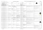
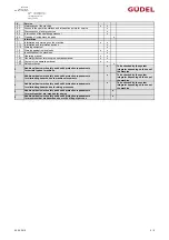
Страница 249: ...Hazard analysis Risk analysis Appendix OPERATING MANUAL MLB 1 3 V2 881017611_v1 0_EN US ...
Страница 250: ...Appendix OPERATING MANUAL MLB 1 3 V2 881017611_v1 0_EN US ...
Страница 254: ...Addition to declaration of incorporation Appendix OPERATING MANUAL MLB 1 3 V2 881017611_v1 0_EN US ...
Страница 255: ...Appendix OPERATING MANUAL MLB 1 3 V2 881017611_v1 0_EN US ...
Страница 258: ...Technical data Appendix OPERATING MANUAL MLB 1 3 V2 881017611_v1 0_EN US ...
Страница 259: ...Appendix OPERATING MANUAL MLB 1 3 V2 881017611_v1 0_EN US ...
Страница 260: ...Layout Appendix OPERATING MANUAL MLB 1 3 V2 881017611_v1 0_EN US ...
Страница 261: ...Appendix OPERATING MANUAL MLB 1 3 V2 881017611_v1 0_EN US ...
Страница 262: ...Spare parts lists Appendix OPERATING MANUAL MLB 1 3 V2 881017611_v1 0_EN US ...
Страница 263: ...Appendix OPERATING MANUAL MLB 1 3 V2 881017611_v1 0_EN US ...
Страница 264: ...Options Appendix OPERATING MANUAL MLB 1 3 V2 881017611_v1 0_EN US ...
Страница 265: ...Appendix OPERATING MANUAL MLB 1 3 V2 881017611_v1 0_EN US ...
Страница 266: ...Third party documentation Appendix OPERATING MANUAL MLB 1 3 V2 881017611_v1 0_EN US ...
Страница 267: ...Appendix OPERATING MANUAL MLB 1 3 V2 881017611_v1 0_EN US ...
Страница 282: ...GÜDEL AG Industrie Nord CH 4900 Langenthal Switzerland Phone 41 62 916 91 91 info ch gudel com www gudel com ...


