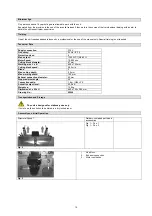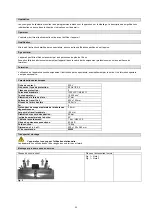
Fig. 4
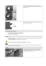
The shaft lock must be pulled out and turned in corresponding
position to unlock or lock the shaft. In the position, the shaft may be
locked (see Fig.).
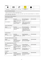
Fig. 5
Attach the unit on a flat horizontal area using matching screws and
check the firm unit positioning.
Initial Operation Safety Instructions
•
Mind the safe attachment of the unit to a suitable surface.
•
Make sure that all the threaded joints are tightened.
•
Check that the motor vents are free.
Procedure
•
Assemble the individual parts in depicted sequence. While proceeding with that, mind the arrangement of structural parts
according to the pictures.
•
Connect a corresponding dust extractor to the exhaust connection.
The shaft protection should be enabled before switching the unit on (Fig. 4).
Always operate the unit with exhaust. Firstly, it will prevent excessive formation of dust that may be health hazardous and
secondly, it provides for better planing results.
Operation
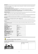
Fig. 6
To release the locking element, the clutch has to be pressed in the
arrow direction and the cover lifted off. The unit will be put in
operation by pressing the button (I). The unit will be switched off by
pressing button (0) and closing the cover.
16


