background image

Geophysical Survey Systems, Inc. 

StructureScan™ Mini XT 


Manual 


MN 70-813 Rev E 

15 

Section 5: Using the ScanMax App 

ScanMax is a 2D data collection program. You will have much greater control over data collection 
parameters, gain, and filtering in ScanMax than in ScanEZ. Please note that ScanMax is accessible only 
when in the Standard or Advanced UI setting. 

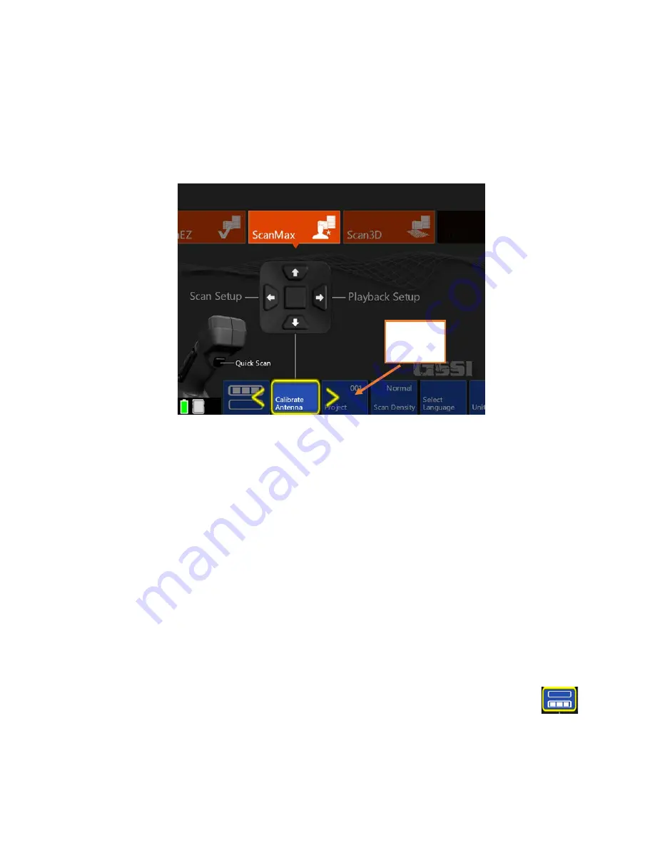
When using ScanMax for the first time, you may want to set some overall, global settings in the menu 
carousel. 

 
On the primary (top) level of the menu carousel, you will have the following options to set: 


Project:

 Choose one of six project folders in which to store your data. This will help to keep files 

organized. Note that files collected in one project will not be visible when the Mini XT is set to a 
different project. 


Scan Density: 

Set the number of scans per inch (cm). Normal = 10/in (4/cm) and  

High = 20/in (8/cm). 


Select Language: 

Choose your desired language. 


Units:

 Choose from Metric or English (Imperial). 


Clear Storage:

 Erase all data stored on the Mini XT in all project folders at once. 


Version Control:

 Allows you to see your current software and firmware versions. This is also 

where you will go to update software/firmware. See Appendix C for more instructions on updating 
your Mini XT. 


Calibrate Antenna:


This will calibrate your Mini XT’s system gain and antenna surface position. 

GSSI recommends that you periodically re-calibrate your Mini XT. 

In the secondary (bottom) level of the carousel, you will have the following options:  


Save Prompt: 

Turning this “On” will cause the Mini XT to ask at the end of each file if 

you want to save. The Mini XT will save each file automatically if this option is set to “Off.” 


Backlight: 

Change the screen brightness in 25% increments. 

Menu 

Carousel 

Содержание StructureScan Mini XT

Страница 1: ......

Страница 2: ...ng the right of reproduction in whole or in part in any form Published by Geophysical Survey Systems Inc 40 Simon Street Nashua New Hampshire 03060 3075 USA Printed in the United States SIR RADAN UtilityScan and PaveScan are registered trademarks of Geophysical Survey Systems Inc ...

Страница 3: ...assign an RMA number Be sure to have the serial number of the unit available Regulatory Information The use of GSSI antennas is governed by different regulatory agencies around the world Specific antenna models must be certified for legal operation in your country Please read and understand the following regulatory passages that pertain to your antenna A listing of certified antennas by region can...

Страница 4: ...ions réglementaires L utilisation des antennes GSSI est régie par différents organismes de réglementation à travers le monde Certains modèles d antenne spécifiques doivent être certifiés pour un fonctionnement légal dans votre pays Merci de lire et comprendre les passages suivants de réglementation qui s appliquent à votre antenne Une liste des antennes certifiées par région peut être trouvée sur ...

Страница 5: ...led operational areas to the FCC Office of Engineering and Technology who shall coordinate this information with the Federal Government through the National Telecommunications and Information Administration The information provided by the UWB operator shall include the name address and other pertinent contact information of the user the desired geographical area of operation and the FCC ID number ...

Страница 6: ...Geophysical Survey Systems Inc StructureScan Mini XT Manual ...

Страница 7: ...ederal Communications Commission FCC requires that all users of GPR who purchased antennas after July 15th 2002 register their equipment and areas of operation It is required that you fill out this form and fax or mail to the FCC Failure to do this is a violation of Federal law 1 Date 2 Company name 3 Address 4 Contact Information contact name and phone number 5 Area Of Operation state s Continued...

Страница 8: ...uency List all antennas being registered Model Frequency FCC ID QF7 followed by Model MINIXT 2700 MHZ QF7MINIXT 7 Receipt Date Of Equipment Fax this form to the FCC at 202 418 1944 Or Mail to Frequency Coordination Branch OET Federal Communications Commission 445 12th Street SW Washington D C 20554 ATTN UWB Coordination Do not send this information to GSSI ...

Страница 9: ...g Device shall be operated only by law enforcement agencies scientific research institutes commercial mining companies construction companies and emergency rescue or firefighting organizations Cet appareil de radar de structure murs poutres dalles ne doit être utilisé qu en contact avec la structure ou à 20 cm maximum décollé de cette structure Cet appareil de radar de sol ne doit être utilisé que...

Страница 10: ...l Profiler EMP 400 Description Electromagnetic Induction System European Standards EN61326 1997 A1 1998 A2 2001 Place and Date of Issue Intertek ETL SEMCO 08 29 06 Model FGDC 3000 2100 StructureScan EZ System StructureScan MINI System StructureScan MiniXT StructureScan EZXT Description Ground Penetrating Radar Data Acquisition Systems European Standards EN61000 6 2 2005 EN61000 4 2 EN61000 4 3 EN6...

Страница 11: ...ax App 21 Section 7 Using the DualScan App 24 Section 8 Using the Palm XT 27 Section 9 File Management 29 Chapter 2 Using RADAN for StructureScan Mini 31 Setting up Your Laptop PC and Data Transfer 31 Launching and Navigating the Software 32 Viewing and Processing the Data 34 Processing the Data 36 Ribbon Options 38 Home Ribbon Options 38 3D Volume Options Ribbon 44 Appendix A The Dielectric Const...

Страница 12: ...Geophysical Survey Systems Inc StructureScan Mini XT Manual ...

Страница 13: ...Tool to remove the XT s handle Safety wrist strap Data collection grids sample pack Quick Start Guide About this Manual This document is the exhaustive user s guide for the Mini XT As such it incorporates the information in the printed Quick Start Guide as well as information for those applications not described in the Quick Start This manual also discusses tips and tricks for processing and prese...

Страница 14: ... Mini XT Front Top View Back View 1 Ergonomic removable handle and controls 2 Easy to use operator interface with color display screen 3 Survey wheel encoder 4 Guiding laser for locating 5 Accessory attachment point 1 2 3 4 5 1 Power button 2 Battery slot 3 USB port 4 Battery release 3 2 1 4 ...

Страница 15: ...he battery tabs 4 Push the Power Button to turn on the Mini XT The Mini XT is powering up and on when the Blue ring on the button is illuminated After a few moments the Mini XT Main menu screen will appear Note The Mini XT incorporates a power saving Sleep feature The Mini XT is asleep when the screen goes black and the blue ring around the power button pulses Pushing any of the buttons on the han...

Страница 16: ...u carousel and then the Left Right arrows to choose Select Language Click the middle keypad button or press the softkey on the carousel to select Choose your desired language This may cause the Mini XT to restart 2 Set Units In the ScanMax App choose Units from the menu carousel Click the middle handle keypad button to press the softkey to toggle between English Imperial and Metric units 3 Calibra...

Страница 17: ...ction depth a little deeper than required 2 Set Concrete Curing Level GPR energy travels at different speeds though concrete which is at different cure levels Setting this accurately will allow for more accurate depth readings These names refer to the concrete s cure not any surface water See Appendix A in this guide for details 3 Choose Color Table This will set the data display color GSSI recomm...

Страница 18: ...a new one The file number in the top left corner will advance by 1 Mark This will write a red dashed user mark to the scan that is being written when the option is pushed This is useful to note the location of something you want to remember Close File This will stop and save the current file and return you to the ScanEZ menu screen While using the Backup Cursor the menu carousel will have the foll...

Страница 19: ...cate and mark out objects in 2D 1 From the ScanEZ Main menu pull the trigger or select Scan from the handle keypad to begin Roll the Mini XT along the area to be scanned The system will display data in real time as you are rolling it 2 Back the Mini XT up in a straight line You will see a yellow vertical line the backup cursor appear on the screen The position of this cursor is tied to the Mini XT...

Страница 20: ...rvey lines in each direction and connect your marks to draw what is in the slab on the slab Note GPR does not provide object size so GSSI recommends that you draw 2 inch 5 cm thick line covering your drawn markouts so as to provide a safe margin near any objects Direction of steel 2 5 cm margin of safety ...

Страница 21: ...uchscreen to browse files 3 Select the file s you want scrolling them to the top of the list and clicking the center handle keypad button or touching the box to the left of the file name 4 Display the file by clicking the Left arrow to activate the handle keypad and then down to play back the data 5 To scroll through very long files select Cursor from the Menu Carousel You will see crosshairs on t...

Страница 22: ... Main menu click the Down arrow on the handle keypad to activate the Menu Carousel You will see the screen at the right Select the following parameters Grid Choose the desired grid size Auto Target The Mini XT will attempt to auto locate objects GSSI recommends leaving this OFF during collection It can be applied during Playback if desired Viewpoint This determines how the onscreen template grid w...

Страница 23: ...cording when it receives enough data 4 Pick up the Mini XT and position it at the beginning of the next line Pull the handle trigger to start the Mini XT recording Wait for the Mini XT to beep before moving 5 When you are finished with the final X direction line move on to the Y direction and continue the process until you have collected all of the lines 6 Select Close Grid from the Menu Carousel ...

Страница 24: ...n 1 cm Thick 2 4 cm and Full thickness A full thickness slice has the top locked at the surface and you can move the bottom of the slice This is useful if you want to core all the way through the slab and need to see everything in one view like an X ray image Viewpoint Toggles through the multiple grid views plus the 2D linescan image Grid Line Toggles to the individual lines in the grid which are...

Страница 25: ... as a tool for tightening up the 3D image Migration requires you to have the correct dielectric value of the concrete The best way to do this is to take a test scan in the ScanMax app and use one of the depth calibration methods to calculate the correct value Please see the ScanMax section for details If you do not know the dielectric then you can modify it during while playing back data Toggle to...

Страница 26: ...rill The Mini XT will analyze the current location for any high amplitude features If none are observed in the current position at the chosen diameter the hole will change from yellow to green If the XT finds any high amplitude features the hole will change from yellow to red NOTE This feature is not a substitute for careful analysis by a trained operator Ø Toggles the diameter of the drill hole i...

Страница 27: ...nt project Scan Density Set the number of scans per inch cm Normal 10 in 4 cm and High 20 in 8 cm Select Language Choose your desired language Units Choose from Metric or English Imperial Clear Storage Erase all data stored on the Mini XT in all project folders at once Version Control Allows you to see your current software and firmware versions This is also where you will go to update software fi...

Страница 28: ...y and sets it to detect 50 or 60 Hz The LineTrac hardware is a separate purchase Please contact your GSSI Sales Rep for details UI Mode This option sets the user interface mode The Mini XT has three modes into which the scan apps are grouped Simple Mode ScanEZ Standard Mode Scan EZ ScanMax Scan3D Advanced Mode ScanEZ ScanMax Scan3D DualScan Setting up Collection Parameters After selecting Scan Set...

Страница 29: ...ope trace Zoom This will perform a horizontal zoom stretch on your data This function can also be accessed while you are scanning Once you have your collection parameters configured as desired click Up to highlight the handle keypad and then click Forward Scan to begin scanning Collecting Data Clicking Scan from the Scan Setup screen previous section will transition the Mini XT to the data collect...

Страница 30: ...elow for more on Focus Mode Calibrate This will allow you to perform three different types of depth calibration on your data See Section 6 more details Close File This will stop and save the current file and return you to the ScanMax menu screen Mark This will write a red dashed user mark to the Backup Cursor location when the option is pushed This is useful to note the location of something you w...

Страница 31: ...e signal may be dampened if the wire is sheathed in a metal conduit LineTrac is passive and does not emit any signals or energy The use of LineTrac will not affect your StructureScan Mini XT data quality in any way 1 Find the LineTrac option in the secondary menu of the Scan Max carousel 2 Click the middle keypad button to toggle to your location s AC frequency 3 Configure the rest of your collect...

Страница 32: ...use the StructureScan Mini XT s backup cursor function to identify the hyperbola belonging to the likely conduit The above image is of the same area as the preceding image but this time the appliance connected to the conduit has been powered down Note the absence of any large standout peaks The LineTrac is recording diffuse background noise and detecting no flowing current ...

Страница 33: ...ity based on a known depth and time This is also known as ground truth It is the most accurate calibration method because it is based on empirical measurements Blank Clicking the middle button on the handle keypad will leave this menu and return to the previous menu Set Dielectric Use a hyperbola fitting tool to model the shape of the actual data image This uses a process called migration to calcu...

Страница 34: ...to which you know the depth 2 Use your finger to move the horizontal crosshair so that the peak in the A scan O scope at the left side of the screen representing the top surface of the object is bisected For a metal object this will be the positive peak 3 Select Calibrate from the menu carousel and then select Set Depth 4 Highlight Step and click the middle keypad button to select a fine or coarse...

Страница 35: ...the dielectric value 5 Match the shape of the blue hyperbola template to the actual hyperbola in the data 6 Click Accept when done Using Auto Depth The Auto Depth option is designed to calibrate for depth by automatically calculating the concrete dielectric Auto Depth is designed to return a dielectric value that is within 0 5 of the actual dielectric value Like Set Dielectric Auto Depth requires ...

Страница 36: ...ax mode Setting Up for Data Collection and Choosing a Base File DualScan uses a reference Base file If you have no 2D files saved on the system from DualScan or any of the other 2D modes the XT will prompt you to collect a new Base file If you have 2D files stored on the XT you will need to specify one of the saved files to act as the Base file The image at the right shows the scan setup screen No...

Страница 37: ...e Base file for any scans in excess of the Base file If you do not have a saved Base file 1 Click Scan from the Scan Setup screen and collect a file GSSI suggests marking the location of the side lasers on the concrete so that you can line up successive comparison files This first file will be your base file Click Close File when you have finished your Base file You will be returned to the Scan Se...

Страница 38: ... Main Menu screen 2 Next click Files from the Playback Setup screen 3 Click Right to activate the file list and scroll to the file list Click the middle keypad button to select the first file This will be the Base file A green check will appear next to the file name 4 Scroll to find the Comparison file and click the middle keypad button to select it A white check will appear next to the file name ...

Страница 39: ...ent for assembly instructions Once the Palm XT is attached to the StructureScan Mini XT you may power the unit on and use it as you would normally The menu options and modes ScanEZ ScanMax Scan3D DualScan will remain the same Please refer to the appropriate section of the manual for specific information on each mode The Palm XT has all of the same controls as the normal XT handle The trigger key i...

Страница 40: ... emphasizes metallic objects like rebar and wire mesh Side Car Mode Transitions the survey wheel to the side of the antenna and allows it to fit into smaller spaces Transitioning between these modes only requires the user to reposition the survey wheel There is nothing in the software to change so the user can freely transition between these modes in the same collection area when necessary Simply ...

Страница 41: ...ternal hard drive 3 Click the Right arrow to access the file list You will see a yellow arrow appear next to the first file You can click up down to browse files or swipe with your finger 4 Align the desired file with the yellow arrow and click the Right arrow or tap the box to the left of the filename to select 5 Once all desired files are selected click the Left arrow twice to the command list U...

Страница 42: ...Geophysical Survey Systems Inc StructureScan Mini XT Manual MN 70 813 Rev E 30 ...

Страница 43: ...for each of your projects To create a new folder right click on your Windows Desktop and select New Folder Give the folder a unique name However if you are comfortable with PCs and Windows you can organize your folders however you wish Transferring the Files Copy the files you wish to view and or process from the StructureScan Mini XT to the PC Laptop See Chapter 1 Section 8 for more information a...

Страница 44: ...i XT Manual MN 70 813 Rev E 32 Launching and Navigating the Software Launching the Software Launch RADAN for StructureScan Mini by double clicking the icon The following screen is displayed 1 GSSI Button 2 Ribbon 3 Data Pane 4 Properties Pane 1 3 4 2 ...

Страница 45: ...ructureScan Mini Software 2 Ribbon This area contains all the options and processes you can do with your data This is also where you may open save or close a file This is detailed more in the Viewing and Processing the Data section 3 Data Pane This is where your data is displayed when you open a file 4 Properties Pane This area will display Global Settings for all your files in a particular projec...

Страница 46: ...ce original data Output Directory Click here then click on the three dots to browse to the output folder you created from your source folder You will not see this option if you have set your Auto Save File to Yes Marker Style Short Display user marks extending down a short distance from the top of the scan Long Display user marks extending through entire scan None Hide all marks Horizontal Scale S...

Страница 47: ...igned specifically for data collected with the StructureScan Mini and Mini XT and includes the ability to instantly process data do some additional processing add interpretations and export to a jpg or excel to quickly generate a report If any other RADAN modules have been purchased they will appear here as additional display options Opening a File 1 Click the Open icon located on the left side of...

Страница 48: ...ocessed file to the Output folder and name the new file as FileName Processed X where X represents the number of times the original file was opened and processed If you have configured Auto Save file set as No the software will process the file however will ask you to save the processed file You may save the file using the software s naming style Or you may rename the file to your style and save t...

Страница 49: ... XT Manual MN 70 813 Rev E 37 The Properties Screen now displays Header information which is information about the file You may click on the left and right arrows located at the bottom of the scale to toggle through the different profiles of your data ...

Страница 50: ...e Close the file located in the current tab Processing Options Focus When the software automatically processes your data it will use the dielectric number you configured and used when the data were collected This value may or may not give you the optimum 3D display The objects displayed in the 3D view may look blurred or blobby You can use the Focus option to re adjust the dielectric for better de...

Страница 51: ...olas Increase the velocity bar by sliding it to the right This will automatically decrease the dielectric The picture in the middle has upside down hyperbolas Decrease the velocity by sliding it to the left This will automatically increase the dielectric The picture on the right has no hyperbolas Dots are present 5 Click on the Process Icon to process the data 6 Save the data if prompted to do so ...

Страница 52: ...on Displays Once a file is open the Global Parameters cannot be changed Window Settings The Properties Pane automatically updates with window specific settings based on which data display 2D or 3D is currently selected Interactive 2D Perform the following steps on the 2D profile and not on the 3D View Add Del Targets This will allow you to tag targets with a dot Simply turn this on and left click ...

Страница 53: ...y Gain Change the contrast brightness of your data This changes the display only it does not change the actual data Targets Turn the display of the targets dots on or off Export 2D Targets Export targets dots information distance depth to a comma delimited ASCII file The name of the file is FileName X csv located in the output folder JPEG Save the current file as a JPEG file Picture File This file...

Страница 54: ...a single page but there will be a loss of resolution Print Page Headers Print Header information Continuous Page If data takes more than one page print data on multiple pages or one page Load Logo Load and print your own logo or GSSI logo Print Preview Preview the printout on screen before actually printing the data Help Index Opens the RADAN for StructureScan Mini Manual About Display the current...

Страница 55: ...o Negate Change negative to positive and positive to negative Drill Hole Enter a tube to represent a hole or core New Target Click here to add targets to your 3D Grid o Click on New Target o Double click on one end of a target o Double click on the other end of a target o Repeat process for more targets 2 Right click on a Target to a Delete Delete the target b Target Properties Name the target cha...

Страница 56: ...oggle between displaying the targets GPR Data Toggle between displaying the data of the 3D Grid Display Gain Adjust the display gain contrast Background Toggle between a black background and white background Export JPG Export the 3D grid as a JPG file Excel Create a report in Microsoft Excel with user entered information data information and a picture of the 3D Grid a Enter information if needed C...

Страница 57: ...tween the antenna sending out the RADAR pulse and then receiving the reflection Since we know for how long the pulse traveled if we can calculate the speed at which it traveled we can calculate how far deep it went How do I know the Dielectric Constant You can start off by estimating the number based on the age of the slab That is what the chart below is for The Mini XT also has a function called ...

Страница 58: ...Geophysical Survey Systems Inc StructureScan Mini XT Manual MN 70 813 Rev E 46 ...

Страница 59: ... Mesh This image shows a section of 6 wire mesh There are two main clues here 1 The even spacing 2 The change in depth Since mesh is produced in a factory to have a constant spacing 6 is typical the spacing between the hyperbolas which denote the wires will be constant Mesh is installed in long rolls and tends to depress as it is weighted down by heavy concrete during the pour The result is often ...

Страница 60: ...e for confirmation When searching for voids behind slabs it is best to collect a long file so that any change such as the black band at the right will be more readily visible Rebar This image is of 8 1 diameter rebar spaced 12 30 cm apart Compare this image to the previous two examples Notice that while there is a constant spacing the spacing is too wide for normal wire mesh Also when surveying ov...

Страница 61: ...o image so we are reflecting off of the air void within the conduit This produces a negative black response since the energy is traveling from a higher dielectric concrete to a lower dielectric air in the same manner as the void example earlier If the PVC conduit were filled with wire or liquid the image would more closely resemble the rebar image since there is now less air by volume in the condu...

Страница 62: ...oint between two adjacent blocks The marks show up on the right as the vertical red dotted lines Between each pair of marks is one block Each CMU has two open cells Those show as the large black areas near the top of the image Blocks with two empty cells have a pair or black areas between the marks Filled cells do not have a black area since the fill material is close in dielectric to the block it...

Страница 63: ...ur runtime battery life dependent on level of display brightness and usage Data Format RADAN dzt Languages English French Japanese Chinese Environmental Operating Temperature 4 F to 104 F external 20 C to 40 C Storage Temperature 40 F to 140 F external 40 to 60 C Relative Humidity 95 non condensing Environmental IP 65 Rated Mechanical Dimensions 9 3 x 6 2 x 7 3 in 23 6 x 18 4 x 15 7 cm Weight 4 lb...

Страница 64: ...Geophysical Survey Systems Inc StructureScan Mini XT Manual MN 70 813 Rev E 52 ...

Страница 65: ...ll of the functionality of the standard Mini XT handle The GSSI part number for the pole is FGSSX POLE Assembly 1 Using the tool provided with the Mini XT loosen the four 4 screws at the base of the Mini XT s handle 2 Lift the handle off of the Mini XT and set aside taking care not to damage the gold toned contacts on the underside of the handle 3 Set the pole s connection plate on the Mini XT on ...

Страница 66: ...the tool provided with the Mini XT remove the black protective plate located below the laser aperture on the front of the Mini XT This will expose the gold colored contacts Take care not to lose the two screws which secure the plate 3 Slide the small eye hole on the top of the LineTrac module over the front guide post 4 Using the provided tool tighten down the two screws This will secure the LineT...

Страница 67: ...e battery has been removed 2 Using the tool provided loosen the four screws attaching the handle to the Mini XT and remove it 3 Carefully place the base of the Palm XT onto the area previously occupied by the handle Make sure that the black cable faces away from the screen The pins at the base of the Palm XT are delicate Be careful not to bend them when placing and removing the accessory 4 Using t...

Страница 68: ...Geophysical Survey Systems Inc StructureScan Mini XT Manual MN 70 813 Rev E 56 ...

Страница 69: ...n government requires that the Mini XT pass emission testing in much the same manner as the FCC The Mini XT ID number is presented here in case Canadian users need to prove that the Mini XT conforms to Canadian government emission regulations FDA The use of lasers in this product is governed by the US Food and Drug Administration The StructureScan Mini XT conforms to FDA Laser Notice No 50 WiFi An...

Отзывы: