


English (GB)
20
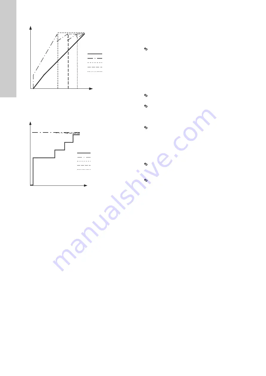
Fig. 25
Regulation curve for MPC-F system in open loop
Fig. 26
Regulation curve for MPC-S system in open loop
Setting range
These settings must be made in connection with open loop:
• Open loop
• Set setpoint 1, open loop
• External setpoint influence
• Normal.
Setting via control panel
Proceed as follows to set an external control source to control the
system:
• Operation > Further settings > Control mode.
• Select: Open loop.
• Select: Stop
1.
x 2.
2. Set to 100 %: Set setpoint 1, open loop.
3. Settings > Primary controller > External setpoint influence >
Go to setting of analog input.
4. Select analog input and range.
5. Select:
• Measured input value.
Display 4.3.8.1.1 appears.
• Select: 0-100 % signal.
6.
.
7. Set the minimum and maximum sensor value.
8.
x 2.
9. Select:
• Input value to be influenced by
• 0-100 % signal.
10.
.
11. Select: Set the influence function.
(See also section
.)
12. Set the number of points.
13. Set: External input value. (Point 1.)
14. Set as a percentage: Reduce setpoint to. (Point 1.)
15. Repeat steps 13 and 14 for all selected points.
16.
.
17. Set as seconds: Filter time.
18. Select: Enabled.
19.
x 2.
20. Select:
• Operation
• Normal.
The booster system can now be controlled by an external
controller.
Factory setting
Closed-loop control.
TM
03 997
5 480
7
TM
03
99
74
48
07
100
50
70.7
5
25
50
75
100
86.6
Input [%] from
external controller
Flow rate [m
3
/h]
Pump 1
Pump 2
Pump 3
Flow rate
Pump 4
100
50
70.7
5
25
50
75
100
86.6
Flow rate [m
3
/h]
Input [%] from
external controller
Pump 1
Pump 4
Pump 3
Flow rate
Pump 2


