User Guide
Lubricus Controller
LUB-C-1, LUB-C-2, LUB-C-3, LUB-C-4,
LUB-C-1-1
(24 VDC)
Lubricus Type C
Страница 1: ...User Guide Lubricus Controller LUB C 1 LUB C 2 LUB C 3 LUB C 4 LUB C 1 1 24 VDC Lubricus Type C...
Страница 2: ...11 12 Activation of exits Pump specific adjustment 10 12 Inputting the generation of the Lubricus C devices used 13 Table pause time adjustments 14 Table quantity adjustment 14 Details Activation Sta...
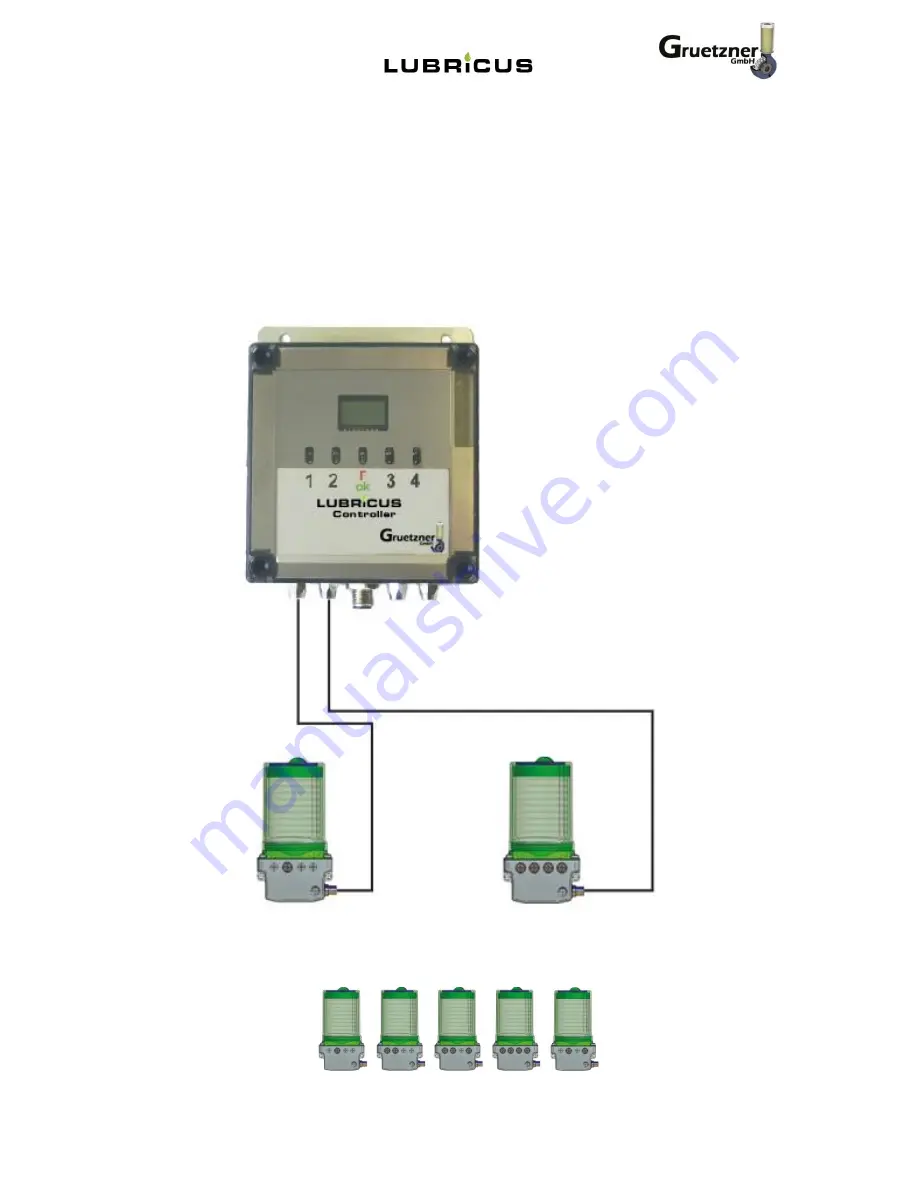
Страница 3: ...e installed in a central location Depending on the configuration of Lubricus Lubrication System Type C is available with up to four outlets and therefore suitable to lubricate several lubrication poin...
Страница 4: ...the clear housing to remove the key for Setup or Adjustments of your Lubricus Simply turn clockwise to release key The point of the key is used for programming Please note Always replace the key for...
Страница 5: ...ccessories and by observation of all installation operation and maintenance instructions Gr tzner GmbH excludes all liability if these instructions are not observed Gr tzner GmbH grants guarantees con...
Страница 6: ...directly on the machine must be strictly followed and maintained in completely readable condition Qualification and training of the personnel The operation maintenance service and installation personn...
Страница 7: ...th the manufacturer Original spare parts and accessories authorized by the manufacturer are for safety purposes Using other parts results in loss of liability for claims resulting out of this For comp...
Страница 8: ...al connection Have the electric power supply connected only by a trained electrician Connection and wiring of the electric components should be done by an expert trained in this field Check the voltag...
Страница 9: ...stallation Lubricus Controller settings Observe the safety instructions The programming mode enables Lubricus will be installed near the lubrication point Entering the quantity of exits per Lubricus I...
Страница 10: ...page 10 Adjustment Flow chart...
Страница 11: ...exit activated A01 1 exit activated A02 2 exits activated Settings for every specific Lubricus Models Type LUB C 1 adjustment at green LED left Lubricus body 1 exit A01 adjustment at orange LED right...
Страница 12: ...Lubricus body 2 outlets is dispensing equal quantity Typ LUB C 4 adjustment at green LED left Lubricus body 2 exits A02 adjustment at orange LED right Lubricus body 2 exits A02 Left and right side of...
Страница 13: ...parameter on the controller as all Lubricus controllers with n01 r03 software are set to the PU2 generation on delivery In accordance with this Pu2 is shown on the display After approx 4 seconds the d...
Страница 14: ...bricus 1 side of body H Pause Time adjustment Time between 2 lubrication intervals 1 to 96 h possible H Pause Time hours 1 12 24 48 96 Result Lubrication cycles per exit per month 720 60 30 15 7 5 Int...
Страница 15: ...orange LED Lubricus unit 2 green LED than orange LED Lubricus unit 3 green LED than orange LED Lubricus unit 4 green LED than orange LED Basic settings all Controller exits are not activated 3 After d...
Страница 16: ...tment at green LED left side of Lubricus body 2 Exits A02 Touch sensor shortly with programming key until required information is displayed If there is no change the displayed value will be used After...
Страница 17: ...es from 15 This is accurate enough to establish the condition of the lubrication point 5 Additional functions QuickCheck extra dispensing cycle pumping of small amounts of lubricant for testing purpos...
Страница 18: ...when the sequence of the connected pump with the error is reached If the sequence reaches the units without error the display will show ON the red LED will still light to signal that an error message...
Страница 19: ...nnected units will dispense as per program in memory Corrective action Change or connect cable broken missing or disconnected connection cable Switch unit OFF and On again The error message will be re...
Страница 20: ...Imax approx 350 mA during pump operation typically 200 mA Standby current standby mode 20 mA Input Signal can switches ON and OFF PIN 2 no assignment PIN 3 Ground GND PIN 4 High operating mode OK inpu...
Страница 21: ...serve the safety instructions Switch off Lubricus Controller 2 Take out ventilation locking turn clock wise to OPEN 3 Press the housing turn left and remove it 4 Remove the empty cartridge 5 Remove pr...
Страница 22: ...rror report will be deleted Technical Data Lubricus Controller Control micro processor controlled up to 4 Lubricus units Type C can be connected Power supply 24 VDC Power consumption max 300mA typical...
Страница 23: ...m outside and 4mm inside diameter Operating pressure max 70 bar Operating temperature 20 C to 80 C Dimensions max Width x height x depth 112 x 196 x 94 mm Weight without lubricant 1120g Control Lubric...
Страница 24: ...age 24 Mounting Lubricus unit 2 srews 6mm for example M6x40 are required for a safe installation of your Lubricus The optimum clamping force of the screw is 5 Nm 3 points at the back assure a safe hol...
Страница 25: ...re vs to tube length tested with tubes 6 x 4 mm Disposal When disposing lubricant the waste disposal instructions of the lubricant manufacturer must be observed Disposal of Lubricus Lubrication System...