-18-
Model G1015 (Mfg. since 7/99)
11. Slide the drive wheel onto the right-hand
arbor with a drive wheel flange (
3
⁄
4
" center
bore) on each side, then secure it in place
with the remaining
3
⁄
4
"-16 arbor hex nut (see
Figure 13).
Note: It may be necessary to use a dead-
blow hammer to seat the drive wheel onto
the arbor. Take great care not to damage the
drive wheel or the threads of the arbor.
12. Remove the two threaded knobs and flat
washers from the sanding arm assembly,
insert the shaft into the pivot arm tube until
the lock collar rests on top of the tube, as
shown in
Figure 14, then re-install the knobs
and flat washers to hold it in place.
13. Install the quick release lever knob as shown
in
Figure 14.
14. Install the platen bracket onto the pivot arm
with the pre-installed hardware, as shown in
Figure 15.
10. Back out the two set screws in the round
housing of the pivot arm, slide the arm onto
the bracket bushing so that the platen bracket
cap screws are facing to the right, as shown
in
Figure 12, then tighten the set screws to
hold the pivot arm in place.
Note: The pivot arm and bushing are designed
so that the set screws tighten into the grooved
surface of the bushing. This keeps the pivot
arm from sliding off the bushing when using
the tilt feature.
15. Install the sanding platen onto the platen
bracket with the pre-installed hardware, as
shown in
Figure 15.
Figure 13. Drive wheel installed.
Drive
Wheel
Outer Flange &
Arbor Hex Nut
Figure 14. Sanding arm assembly installed.
Threaded
Knobs
Lock
Collar
Sanding Arm
Assembly
Quick Release
Lever Knob
Figure 15. Sanding platen and bracket installed.
Platen
Bracket
Sanding
Platen
Figure 12. Pivot arm installed.
Bushing
Platen Bracket
Cap Screws
Pivot
Arm
Set Screw
Содержание G1015
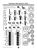
Страница 15: ...Model G1015 Mfg since 7 99 13 5mm Hardware Recognition Chart...
Страница 40: ......


