background image

COPYRIGHT © JANUARY, 2018 BY GRIZZLY INDUSTRIAL, INC. REVISED AUGUST, 2018 (TK)


WARNING: NO PORTION OF THIS MANUAL MAY BE REPRODUCED IN ANY SHAPE

 OR FORM WITHOUT THE WRITTEN APPROVAL OF GRIZZLY INDUSTRIAL, INC.

#19249KB  PRINTED IN CHINA

V1.08.18

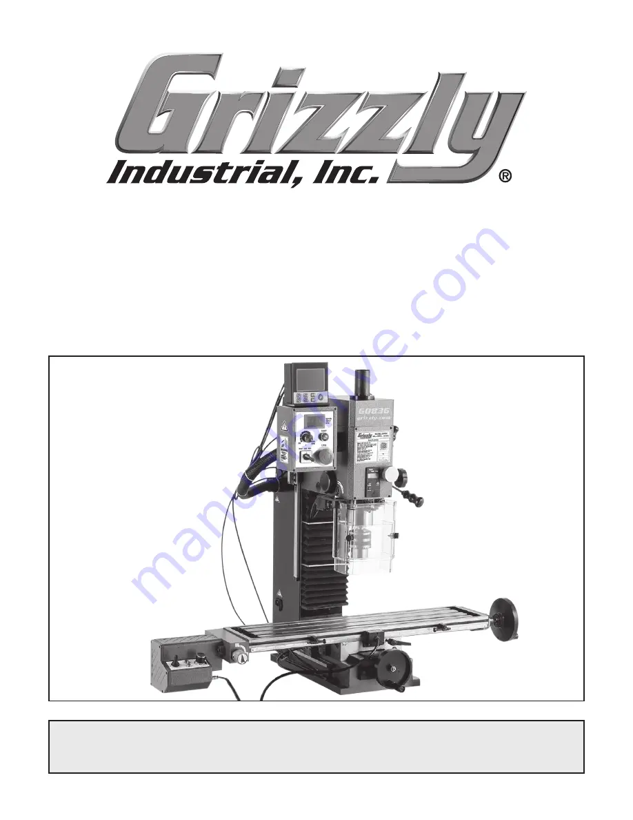
MODEL G0836

MINI MILL/DRILL w/DRO

OWNER'S MANUAL

(For models manufactured since 09/17)

Содержание G0836

Страница 1: ...GUST 2018 TK WARNING NO PORTION OF THIS MANUAL MAY BE REPRODUCED IN ANY SHAPE OR FORM WITHOUT THE WRITTEN APPROVAL OF GRIZZLY INDUSTRIAL INC 19249KB PRINTED IN CHINA V1 08 18 MODEL G0836 MINI MILL DRI...

Страница 2: ...g grinding tool integrity and the usage of personal protective equipment The manufacturer will not be held liable for injury or property damage from negligence improper training machine modifications...

Страница 3: ...RATIONS 23 Operation Overview 23 Spindle Downfeed 24 Adjusting Headstock 26 Controlling Table Travel 26 Installing Removing Tooling 28 Setting Spindle Speed 29 Table of Contents SECTION 5 ACCESSORIES...

Страница 4: ...de every effort to be exact with the instruc tions specifications drawings and photographs in this manual Sometimes we make mistakes but our policy of continuous improvement also means that sometimes...

Страница 5: ...lector Knob Identification Become familiar with the names and locations of the controls and features shown below to better understand the instructions in this manual M Coarse Downfeed Handle N Spindle...

Страница 6: ...n fault occurs Reset by turning spindle speed dial to 0 or by pressing E Stop button J Press to scroll screen right K Press to return to previous screen and to return to main X Y Z axis display screen...

Страница 7: ...r feed encounters fault or power feed limit switch Reset by turning speed control dial OFF Y POWER Indicator Glows green when power feed is connected to power supply Z Speed Control Dial Rotate to tur...

Страница 8: ...Electrical Power Requirement 110V Single Phase 60 Hz Full Load Current Rating 11A Minimum Circuit Size 15A Connection Type Cord Plug Power Cord Included Yes Power Cord Length 6 ft Power Cord Gauge 16...

Страница 9: ...16 20 Drawbar Length 10 in Spindle Bearings Tapered Roller 32907 Construction Spindle Housing Quill Cast Iron Steel Table Cast Iron Head Cast Iron Column Base Cast Iron Base Cast Iron Paint Type Finis...

Страница 10: ...proof DANGEROUS ENVIRONMENTS Do not use machinery in areas that are wet cluttered or have poor lighting Operating machinery in these areas greatly increases the risk of accidents and injury MENTAL ALE...

Страница 11: ...moving parts or flying debris Make sure they are properly installed undamaged and working correctly BEFORE operating machine FORCING MACHINERY Do not force machine It will do the job safer and better...

Страница 12: ...the rotating spindle with great force To reduce your risk of serious injury when operating this machine completely heed and understand the following CLEAN MACHINE SAFELY Metal chips or shav ings can b...

Страница 13: ...sized circuit To reduce the risk of these hazards avoid over loading the machine during operation and make sure it is connected to a power supply circuit that meets the specified circuit requirements...

Страница 14: ...rd size gets longer and the gauge size gets smaller higher gauge numbers indicate smaller sizes Any extension cord used with this machine must be in good condition and contain a ground wire and matchi...

Страница 15: ...Grizzly or the shipping agent You MUST have the original pack aging to file a freight claim It is also extremely helpful if you need to return your machine later Unpacking SUFFOCATION HAZARD Keep chi...

Страница 16: ...ietary parts are missing e g a nut or a washer we will gladly replace them or for the sake of expediency replacements can be obtained at your local hardware store Box 1 Figures 6 7 Qty A Mill Drill Un...

Страница 17: ...ps for removing rust preventative 1 Put on safety glasses 2 Coat the rust preventative with a liberal amount of cleaner degreaser then let it soak for 5 10 minutes 3 Wipe off the surfaces If your clea...

Страница 18: ...ironment where the machine is operated is important for safe operation and lon gevity of machine components For best results operate this machine in a dry environment that is free from excessive moist...

Страница 19: ...est mounting option is a Through Mount see example below where holes are drilled all the way through the workbench and hex bolts washers and hex nuts are used to secure the machine in place Machine Ba...

Страница 20: ...gure 14 Tapping drill chuck arbor on block of wood An arbor is included for the drill chuck that comes with this machine The following procedure describes how to install the arbor in the chuck After t...

Страница 21: ...achine to ensure it is properly connected to power and safety components are functioning correctly If you find an unusual problem during the test run immediately stop the machine disconnect it from po...

Страница 22: ...fore further using the machine Power Feed Test Run This mill drill comes with a power feed unit for X axis table travel see Figure 18 A limit switch and adjustable table limit stops see Figure 19 atta...

Страница 23: ...page to perform the Spindle Bearing Break In and Inspections Adjustments procedures To test run power feed 1 Make sure all tools cables and other items are well clear of table movement and potential d...

Страница 24: ...e in this progressive manner helps minimize any potential wear that could occur before lubrication is fully distributed You must complete this procedure to main tain the warranty Failure to do this co...

Страница 25: ...o perform operation 9 Turns spindle OFF when complete 10 Waits for spindle to completely stop before removing workpiece or changing spindle direction 11 Disconnects mill drill from power before changi...

Страница 26: ...ecome familiar with spindle downfeed controls Figure 23 Location of quill lock controls Quill Lock Hex Wrench Quill Lock To use coarse downfeed 1 Loosen downfeed selector knob to engage coarse downfee...

Страница 27: ...ng a flat surface across the face of a workpiece to ensure the spindle depth does not move until the entire milling operation is complete In the following example the fine downfeed controls are used t...

Страница 28: ...handwheel Z Axis Handwheel Y axis table travel is adjusted with the handwheel on the front of the table base see Figure 29 Figure 29 Y axis table controls Y Axis Handwheel Y Axis Table Lock Z Axis Lo...

Страница 29: ...r feed has exceeded table travel limit or reached an obstruction Reset by turning speed control dial OFF moving direction switch to middle OFF position and eliminating fault condition There is no sepa...

Страница 30: ...d tooling mating surface Do not overtighten drawbar Overtightening makes tool removal difficult and may dam age arbor and threads 3 Align keyway of tool with protruding pin inside spindle taper firmly...

Страница 31: ...g speeds to use when calculating the spindle speed These sources also provide a wealth of additional information about the variables that affect cutting speed and they are a good educational resource...

Страница 32: ...l stand with built in storage G7156 4 35 8 Precision Milling Vise G7154 5 41 2 Precision Milling Vise G7155 6 55 8 Precision Milling Vise Swiveling milling vises feature perfectly aligned precision gr...

Страница 33: ...0 degrees 4A drive motor and a hori zontal table height of 33 4 Figure 42 12 oz South Bend Lathe way oil SB1365 South Bend Way Oil ISO 68 Engineered for the high pressure exerted on horizontal or vert...

Страница 34: ...R8 Collet Set Figure 44 SB1349 South Bend 16 Pc R8 Collet Set T25702 5 Pc R8 End Mill Holder Set This all inclusive set features a precision 3 bor ing head R8 shank five piece set of 3 4 carbide tipp...

Страница 35: ...ver any setup problem Set includes 1 each 3 8 diameter with point 3 8 dia combination with a point and 200 shoulder 1 2 dia with a point and 1 2 dia with 200 shoulder Figure 49 H2939 4 Pc Edge Finder...

Страница 36: ...includes a pair of 1 x 2 x 3 blocks five 3 8 16 stainless steel socket head cap screws and a hex key The steel blocks offer rigidity and stability and are oversized to allow normal tapping from 0001...

Страница 37: ...e 38 Schedule Metal chips left on the machine that have been soaked with water based coolant will invite oxida tion and a gummy residue build up around the moving parts Use a brush and shop vacuum to...

Страница 38: ...1365 or ISO 68 Equivalent Lube Amount Thin Coat Lubrication Frequency 40 Hours of Operation To lubricate table leadscrews 1 DISCONNECT MACHINE FROM POWER 2 Using Y axis handwheel move table as far for...

Страница 39: ...1 Rags As Needed To lubricate column leadscrew and gears 1 DISCONNECT MACHINE FROM POWER 2 Remove 2 Phillips screws securing Z axis DRO sensor strip to column see Figure 62 then carefully remove senso...

Страница 40: ...e Note Re apply oil that may have been removed during the cleaning process to the smooth quill surface around the rack Quill Rack Lube Type T26419 or NLGI 2 Equivalent Lube Amount Thin Coat Lubricatio...

Страница 41: ...erpowered 1 Feed rate cutting speed too fast 2 Machine undersized for task or tooling incorrect for task 3 Wrong cutter type 4 Wrong workpiece material 5 Motor overheated 6 Spindle speed dial at fault...

Страница 42: ...This increases rigidity Table is hard to move 1 Table locks tightened down 2 Chips loaded up on ways 3 Ways are dry and need lubrication 4 Table limit stops interfering 5 Gibs too tight 1 Release tab...

Страница 43: ...mit switch positions Page 26 7 Check gears and adjust replace 8 Replace clutch Operates at high speed only or is inconsistent 1 Wiring harness unplugged from circuit board 2 Speed control dial potenti...

Страница 44: ...e gib while at the same time using the handwheels to move the table until you feel a slight drag in that path of movement Adjusting Leadscrew Backlash Tool Needed Qty Hex Wrench 4mm long 1 Leadscrew b...

Страница 45: ...t at the time of printing but may not match your machine If you find this to be the case use the wiring diagram inside the motor junction box CAPACITORS INVERTERS Some capacitors and power inverters s...

Страница 46: ...sor Guard Limit Switch Motor DRO Control Panel Neutral Hot Ground X Axis Power Feed Table Limit Switch Headstock Column Wiring Overview Component Location DRO Control Panel Machine Column Power Connec...

Страница 47: ...iewed from behind Potentiometer Fault Light PL110V 1 1 2 2 3 Rotary Switch Emergency Stop To Column P1 P2 P3 4 3 110V Motor Clear Guard Limit Switch 5 7 1 9 11 4 6 8 2 10 12 N 1 2 L 11 12 23 24 KEDU Q...

Страница 48: ...5W0 1J Machine Column To Control Panel 5 AC4 DC2 AC3 DC1 P4 P3 P2 P1 7 6 FC750BJ 110V 942H 1A 12DS T Ground P1 P2 P3 7 6 5 2 1 Power Connection Port N L Fuse 10A 250V 110 VAC 5 15 Plug Circuit Board...

Страница 49: ...MOTOR 110V Fault Lamp Power Feed Housing Circuit Board Front View K2 K1 P3 P2 P1 M J1 Limit Switch Housing W P1 P2 P3 P1 P2 P3 K1 K1 K2 Power Lamp Table Direction Switch Potentiometer 3 2 1 KEDU HY29...

Страница 50: ...7 204 206 208 205 191 207 46 51 47 45 23 22 24 79 44 62 78 44 83 10 36 50 12 11 60 72 35 81 211 34 25 73 37 13 33 3 14 27 37 2 7 39 38 175 144 170 171 172 164 173 181 174 180 179 178 177 176 162 164 2...

Страница 51: ...OCK SHAFT 27 P0836027 GEAR SHAFT ADJUSTING WASHER 20 X 28 X 4 85 P0836085 HEADSTOCK HOUSING 28 P0836028 CAP SCREW M10 1 5 X 16 86 P0836086 R8 SPINDLE SLEEVE 29 P0836029 SLEEVE LIMIT WASHER 87 P0836087...

Страница 52: ...355 314 315 316 333 332 334 322 352 353 354 331 348 302 301 361 304 327 312 361 303 325 326 347 350 330 361 307 310 327 306 350 319 309 335 336 341 346 358 344 345 349 305 320 321 363 311 329 328 314...

Страница 53: ...T M8 1 25 319 P0836319 DRAIN PLUG M16 1 5 357 P0836357 READER BRACKET 320 P0836320 CAP SCREW M6 1 X 10 358 P0836358 MAGNETIC PAD READER 321 P0836321 FLAT WASHER 6MM 359 P0836359 PHLP HD SCR M3 5 X 14...

Страница 54: ...454 447 435 451 450 447 449 448 446 453 442 461 427 402 404 403 405 458 472 459 471 470 457 460 469 436 431 462 434 435 433 430 435 432 410 412 417 409 421 428 414 415 429 421 416 408 463 401 406 419...

Страница 55: ...360453 BACK COVER 417 P08360417 ROLL PIN 3 X 20 454 P08360454 PC BOARD FC750BJ 110V 418 P08360418 LIFT NUT 455 P08360455 STRAIN RELIEF TYPE 3 419 P08360419 LIFT LOCK NUT 456 P08360456 PHLP HD SCR M3 5...

Страница 56: ...OTICE FOLLOW SPINDLE BREAK IN PROCEDURES BEFORE OPERATING THIS MACHINE Failure to follow the break in procedures included in your manual will lead to shortened tool life and may void warranty To reduc...

Страница 57: ...metalworker ____ 0 2 Years ____ 2 8 Years ____ 8 20 Years ____20 Years 6 How many of your machines or tools are Grizzly ____ 0 2 ____ 3 5 ____ 6 9 ____10 7 Do you think your machine represents a good...

Страница 58: ...LINE FOLD ALONG DOTTED LINE GRIZZLY INDUSTRIAL INC P O BOX 2069 BELLINGHAM WA 98227 2069 Place Stamp Here Name_______________________________ Street_______________________________ City______________S...

Страница 59: ...shall be tried in the State of Washington County of Whatcom We shall in no event be liable for death injuries to persons or property or for incidental contingent special or consequential damages arisi...

Страница 60: ......

Отзывы: