Model G0654 (Mfg. Since 9/07)
-19-
16. loosen the motor or cutterhead pulley set
screws and move the pulleys in or out as
needed to bring them into alignment.
17. tighten the pulley set screws.
18. lower the motor to increase belt tension,
tighten the motor mount bolts and recheck
pulley alignment.
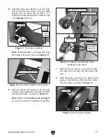
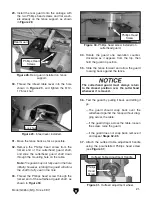
19. install the front panel (figure 19) onto the
cabinet with (10) #10-24 x
3
⁄
8
" flange screws,
making sure the panel is installed on the
same side as the motor fan.
figure 19. Front panel installed.
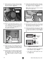
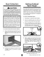
20. install the switch assembly onto the front
panel with (4) #10-24 x
3
⁄
8
" flange screws, as
shown in
figure 20.
figure 20. switch installed.
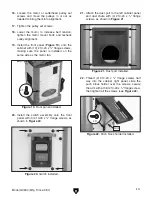
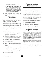
21. attach the dust port to the left cabinet panel
and dust chute with (4) #10-24 x
3
⁄
8
" flange
screws, as shown in
figure 21.
figure 21. dust port installed.
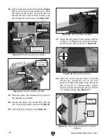
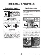
22. thread (2) #10-24 x
3
⁄
8
" flange screws half
way into the cabinet right panel, slide the
push block holder over the screws, secure
the arm with a third #10-24 x
3
⁄
8
" flange screw,
then tighten all the screws (see
figure 22).
figure 22. push block holder installed.
arm
x 10
x 3
Содержание G0654
Страница 56: ......

