background image

Model G0654 (Mfg. Since 9/07)

-47-

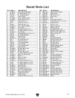
REF PART #

DESCRIPTION

REF PART #

DESCRIPTION

101

P0654101

GIB

145

PSS53M

SET SCREW M5-.8 X 12

102

P0654102

KNIFE

147

P0654147

INDEX PIN M6-1 X 14

103

P0654103

GIB BOLT

148

P0654148

COMPRESSION SPRING

104

P0654104

CUTTERHEAD PULLEY

149

P0654149

PLUNGER HOUSING

105

P0654105

RIGHT HAND BEARING SUPPORT

150

P0654150

BALL KNOB M6-1

106

P6203

BALL BEARING 6203ZZ

151

P0654151

POINTER

107

PK12M

KEY 5 X 5 X 30

152

PS17M

PHLP HD SCR M4-.7 X 6

108

PSS53M

SET SCREW M5-.8 X 12

153

P0654153

PLATE

109

P0654109

SPECIAL NUT

154

P0654154

TORSION SPRING

110

PSS01M

SET SCREW M6-1 X 10

155

P0654155

CUP

111

P0654111

CUTTERHEAD

156

P0654156

RETAINER

112

P6202

BALL BEARING 6202ZZ

157

PS01M

PHLP HD SCR M4-.7 X 18

113

P0654113

LEFT HAND BEARING SUPPORT

158

P0654158

BLOCK ASSEMBLY

114

P0654114

SPECIAL STUD

161

P0654161

LOCK LEVER M6-1 X 30

115

PLW06M

LOCK WASHER 10MM

162

PSBS23M

BUTTON HD CAP SCR M8-1.25 X 25

116

PN02M

HEX NUT M10-1.5

163

PW01M

FLAT WASHER 8MM

117

P0654117

FENCE CARRIAGE

164

P0654164

ALIGNMENT PIN

118

PW04M

FLAT WASHER 10MM

165

P0654165

BRACKET

119

PLW06M

LOCK WASHER 10MM

166

PSB11M

CAP SCREW M8-1.25 X 16

120

PB01M

HEX BOLT M10-1.5 X 30

167

PLW04M

LOCK WASHER 8MM

121

PRP39M

ROLL PIN 4 X 20

168

PEC07M

E-CLIP 7MM

122

P0654122

SPECIAL KEY 9.5 X 9.5 X 128

169

P0654169

LINK

123

P0654123

LOCK SCREW ASSEMBLY

170

P0654170

SPECIAL BOLT

124

PN01M

HEX NUT M6-1

172

P0654172

JOINTER TABLE ASSEMBLY

125

PSS12M

SET SCREW M6-1 X 25

176

PN09M

HEX NUT M12-1.75

126

P0654126

GIB

177

P0654177

INFEED TABLE ADJUSTMENT LEVER

127

P0654127

PUSH BLOCK

179

PSS20M

SET SCREW M8-1.25 X 8

128

PSS02M

SET SCREW M6-1 X 6

180

P0654180

BLOCK

129

P0654129

SPECIAL WASHER

181

P0654181

SHAFT

130

PS14M

PHLP HD SCR M6-1 X 12

182

PEC12M

E-CLIP 12MM

131

PW03M

FLAT WASHER 6MM

184

P0654184

SEAL

133

P0654133

HANDWHEEL

187

PWR810

WRENCH 8 X10

134

P0654134

HANDLE

188

PRW1214

WRENCH 12 X 14

135

P0654135

SHOULDER SCREW

189

PWR1417

WRENCH 14 X 17

136

P0654136

COLLAR

190

PAW02.5M

HEX WRENCH 2.5MM

137

P0654137

SPECIAL WASHER

191

PAW03M

HEX WRENCH 3MM

138

P0654138

BLOCK

192

PAW04M

HEX WRENCH 4MM

139

PLW04M

LOCK WASHER 8MM

193

PAW06M

HEX WRENCH 6MM

140

PSB05M

CAP SCREW M8-1.25 X 50

195

P0654195

KNIFE GAUGE ASSEMBLY

141

P0654141

SCREW SHAFT

195-1 P0654195-1

KNIFE GAUGE ROD

143

P0654143

GUARD SHAFT

195-2 P0654195-2

KNIFE GAUGE BLOCK

144

P0654144

GUARD

195-3 PEC015M

E-CLIP 8MM

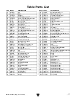
Table parts List

Содержание G0654

Страница 1: ...yright January 2008 By Grizzly Industrial Inc Revised JUne 2013 dm Warning No portion of this manual may be reproduced in any shape Or form without the written approval of Grizzly Industrial inc For machines manufactured since 9 07 BL10265 printed in CHINA ...

Страница 2: ...ng grinding tool integrity and the usage of personal protective equipment The manufacturer will not be held liable for injury or property damage from negligence improper training machine modifications or misuse Some dust created by power sanding sawing grinding drilling and other construction activities contains chemicals known to the State of California to cause cancer birth defects or other repr...

Страница 3: ...Recommended Adjustments 23 Tighten V Belt 23 SECTION 4 OPERATIONS 24 Operation Safety 24 Basic Controls 24 Stock Inspection Requirements 26 Squaring Stock 27 Surface Planing 28 Edge Jointing 29 Bevel Cutting 30 Rabbet Cutting 31 SECTION 5 ACCESSORIES 32 SECTION 6 MAINTENANCE 34 Schedule 34 Cleaning 34 Lubrication 34 V Belt 35 SECTION 7 SERVICE 36 Troubleshooting 36 Inspecting Knives 38 Setting Rep...

Страница 4: ...we make mistakes but our policy of continuous improvement also means that sometimes the machine you receive will be slightly different than what is shown in the manual if you find this to be the case and the difference between the manual and machine leaves you confused about a procedure check our website for an updated version We post current manuals and manual updates for free on our website at w...

Страница 5: ...tterhead Guard E Fence Lock F Fence Tilt Handle G Infeed Table H Infeed Table Adjustment Lever I ON OFF Switch J Push Block Holder K Depth Scale L Infeed Table Lock M Wheel Assembly N Dust Port O Outfeed Table Handwheel P Outfeed Table Lock Q Depth Stop Knob Identification E A C C D E F F G H J I K L M O P B N Q ...

Страница 6: ...ngth x Width x Height 49 x 23 x 16 in Must Ship Upright No Electrical Power Requirement 110V Single Phase 60 Hz Prewired Voltage 110V Full Load Current Rating 14A Minimum Circuit Size 20A Connection Type Cord Plug Power Cord Included Yes Power Cord Length 8 ft Power Cord Gauge 14 AWG Plug Included Yes Included Plug Type 5 15 Switch Type ON OFF Push Button Switch w Large Shut Off Paddle Motors Main...

Страница 7: ...Knife Type HSS Single Sided Knife Length 6 1 8 in Knife Width 5 8 in Knife Thickness 1 8 in Knife Adjustment Jack Screws or Springs Table Information Table Length 46 in Table Width 7 1 2 in Floor to Table Height 33 3 8 in Table Adjustment Type Handwheel Table Movement Type Dovetailed Ways Construction Base Cast Iron Body Assembly Cast Iron Cabinet Pre formed Steel Fence Assembly Cast Iron Guard Di...

Страница 8: ...oof DANGEROuS ENvIRONMENTS do not use machinery in areas that are wet cluttered or have poor lighting operating machinery in these areas greatly increases the risk of accidents and injury MENTAL ALERTNESS REQuIRED Full mental alertness is required for safe operation of machin ery never operate under the influence of drugs or alcohol when tired or when distracted for your Own Safety Read Instructio...

Страница 9: ...educe accidental contact with moving parts or flying debris make sure they are properly installed undamaged and working correctly fORcING MAchINERy do not force machine it will do the job safer and better at the rate for which it was designed NEvER STAND ON MAchINE serious injury may occur if machine is tipped or if the cutting tool is unintentionally contacted STABLE MAchINE unexpected movement d...

Страница 10: ...tation If the outfeed table is set too low the workpiece may rock against the cutterhead If the table is set too high the workpiece may hit the outfeed table and get stuck over the cutterhead INSPECTING STOCK To reduce the risk of kickback injuries or machine damage thoroughly inspect and prepare the workpiece before cutting Verify the workpiece is free of nails staples loose knots or other foreig...

Страница 11: ...ized circuit to reduce the risk of these hazards avoid over loading the machine during operation and make sure it is connected to a power supply circuit that meets the requirements in the following section for your own safety and protection of property consult an electrician if you are unsure about wiring practices or electrical codes in your area Note The circuit requirements listed in this man u...

Страница 12: ...shock The wire with green insulation with or without yellow stripes is the equipment grounding wire If repair or replacement of the power cord or plug is nec essary do not connect the equipment grounding wire to a live current carrying terminal Check with a qualified electrician or service per sonnel if you do not understand these grounding requirements or if you are in doubt about whether the too...

Страница 13: ...its parts To reduce this risk get help from other people and use a fork lift or other lifting equipment rated for weight of this machine Your machine was carefully packaged for safe transportation Remove the packaging materials from around your machine and inspect it If you discover any damage please call us immediately at 570 546 9663 for advice Save the containers and all packing materials for p...

Страница 14: ...Knife Setting Jig 1 Y Outfeed Table Adjustment Handwheel 1 Figure 3 Box 1 inventory contents A B C D E F G H I J K L Figure 4 Box 1 inventory contents M X Y N O P Q R S T U V W Inventory The following is a list of items shipped with your machine Before beginning setup lay these items out and inventory them If any non proprietary parts are missing e g a nut or a washer we will gladly replace them o...

Страница 15: ... 2 Leveling Feet Cabinet 2 Carriage Bolts 5 16 18 x 11 8 Motor 4 Flat Washers 5 16 Motor 4 Hex Nuts 5 16 18 Motor 4 Hex Nuts M10 1 5 Jointer Assy 3 Lock Washers 10mm Jointer Assy 3 Flange Screws 10 24 x 3 8 Front Panel 10 Flange Screws 10 24 x 3 8 Switch 4 Flange Screws 10 24 x 3 8 Dust Port 4 Flange Screws 10 24 x 3 8 Push Block Holder 3 Flange Bolt M6 1 x 12 Belt Guard 2 Flat Washers 6mm Belt Gu...

Страница 16: ...ic paint scraper optional Basic steps for removing rust preventative 1 put on safety glasses 2 Coat the rust preventative with a liberal amount of cleaner degreaser then let it soak for 5 10 minutes 3 Wipe off the surfaces if your cleaner degreas er is effective the rust preventative will wipe off easily if you have a plastic paint scraper scrape off as much as you can first then wipe off the rest...

Страница 17: ...he physical environment where the machine is operated is important for safe operation and lon gevity of machine components For best results operate this machine in a dry environment that is free from excessive moisture hazardous chemi cals airborne abrasives or extreme conditions Extreme conditions for this type of machinery are generally those where the ambient temperature range exceeds 41 104 F ...

Страница 18: ...ed to chassis Cabinet Support Chassis Figure 10 Left and right panels installed 4 Secure the left and right panels to the cabinet supports with 20 10 24 x 3 8 flange screws as shown in Figure 10 Note The two holes on the left panel below the dust chute slot should face down The right panel should be installed with the two block holder holes facing up Figure 9 Top plate installed 2 Fasten the botto...

Страница 19: ...so the pulley is flush with the shaft end then tighten the set screws as shown in Figure 14 Figure 14 Motor pulley installed Set Screw Pulley Key 5 Carefully place the cabinet on its left side and secure the dust chute to the top plate flanges and left panel with 6 M6 1 x 12 flange bolts 6mm flat washers and M6 1 hex nuts Figures 11 12 Figure 11 Dust chute installed Left Panel Dust Chute x 6 Top P...

Страница 20: ...gure 17 Note Reach inside the dust chute to secure the stud on the right side Figure 17 Jointer secured to cabinet 14 Slide the motor up place the V belt around the cutterhead and motor pulleys then slide the motor down to rest on the V belt 15 Check the alignment of the pulleys to make sure that they are aligned and that the V belt is straight up and down as shown in Figure 18 Carriage Bolt 5 16 ...

Страница 21: ...n the same side as the motor fan Figure 19 Front panel installed 20 Install the switch assembly onto the front panel with 4 10 24 x 3 8 flange screws as shown in Figure 20 Figure 20 Switch installed 21 Attach the dust port to the left cabinet panel and dust chute with 4 10 24 x 3 8 flange screws as shown in Figure 21 Figure 21 Dust port installed 22 Thread 2 10 24 x 3 8 flange screws half way into...

Страница 22: ...in Step 23 26 Install the fence tilt lever see Figure 25 Key Fence Lock Handle Carriage Lock Nut Flat Washer Fence Lock Handle Bolt Figure 25 Fence tilt lever installed 27 Install the belt guard on the cabinet with the 2 M6 1 x 12 flange bolts 6mm flat washers and M6 1 hex nuts as shown in Figure 26 Figure 26 Belt guard installed 28 Insert the motor cord and motor cord plate through the rectangula...

Страница 23: ... head screw through the forked end of the cutterhead guard shaft as shown in Figure 30 34 Rotate the guard one revolution counter clockwise as it appears from the top then hold the guard in position 35 Slide the fence forward and allow the guard to swing back against the fence Figure 30 Phillips head screw installed on cutterhead guard 36 Test the guard by pulling it back and letting it go The gua...

Страница 24: ...of the knives is at top dead center TDC see Figure 33 4 When correctly set the knife will just touch the straightedge when the knife is at its high est point of rotation see Figure 34 and the straightedge should move 5 32 toward the infeed table when the cutterhead pulley is rotated Figure 34 Using a straightedge to align outfeed table height with knife at TDC Straightedge 5 32 Outfeed Infeed Sett...

Страница 25: ...m with the machine or V belt Test Run Once the assembly is complete test run your machine to make sure it runs properly If during the test run you cannot easily locate the source of an unusual noise or vibration stop using the machine immediately then review the Troubleshooting on Page 36 If you still cannot remedy a problem contact our Tech Support at 570 546 9663 for assistance To test run the m...

Страница 26: ...tion Grizzly Industrial will not be held liable for accidents caused by lack of training Figure 36 Table control locations Basic Controls This section covers the basic controls used during routine operations START Button Starts motor STOP Paddle Stops motor when pushed in Figure 35 START STOP controls STOP Paddle START Button Table Movement To move the infeed or outfeed tables loosen the table loc...

Страница 27: ... secures the fence at any position in the available range The plunger locks the fence tilt for 90 cuts Two positive stops stop the fence at 45 inward and 45 outward for common 45 bevel cuts Even when the fence is resting against the posi tive stops the tilt lock must be tightened before cutting Also the plunger must be disengaged for 45 outward bevel cuts Figure 38 Tilt lock and swing stop locatio...

Страница 28: ...move foreign objects from the workpiece Make sure that any stock you process with the jointer is clean and free of dirt nails staples tiny rocks or any other foreign objects that could damage the cutterhead These particles could also cause a spark as they strike the cutterhead and cre ate a fire hazard Note Wood stacked on a concrete or dirt surface can have small pieces of concrete or stone press...

Страница 29: ...osite face of the workpiece is sur face planed flat with a thickness planer see Figure 42 Previously Surface Planed Face Figure 42 Surface planing on a thickness planer 3 Edge Joint on the Jointer The concave edge of the workpiece is jointed flat with the jointer see Figure 43 Figure 43 Edge jointing on the jointer 4 Rip Cut on a Table Saw The jointed edge of the workpiece is placed against the ta...

Страница 30: ...g a more shallow depth for hard wood species or for wide stock 4 Make sure the fence is set to 90 5 If the workpiece is cupped warped place it so the concave side is face down on the surface of the infeed table 6 Start the jointer 7 With a push block in each hand press the workpiece against the table and fence with firm pressure and feed the workpiece over the cutterhead Note If your leading hand ...

Страница 31: ...e cutterhead Note If your leading hand gets within 4 of the cutterhead lift it up and over the cutterhead and place it on the portion of the workpiece that is over the outfeed table Now focus your pressure on the outfeed end of the workpiece while feeding and repeat the same action with your trailing hand when it gets within 4 of the cutterhead To keep your hands safe DO NOT let them get closer th...

Страница 32: ...rface of the infeed table 6 Start the jointer 7 With a push block in your leading hand see Figure 49 press the workpiece against the table and fence with firm pressure and feed the workpiece over the cutterhead Note If your leading hand gets within 4 of the cutterhead lift it up and over the cutterhead and place the push block on the portion of the workpiece that is on the outfeed table Now focus ...

Страница 33: ...utterhead guard after rabbet cutting Note If your leading hand gets within 4 of the cutterhead lift it up and over the cutterhead and place the push block on the portion of the workpiece that is on the outfeed table Now focus your pressure on the outfeed end of the workpiece while feeding and repeat the same action with your trailing hand when it gets within 4 of the cutterhead To keep your hands ...

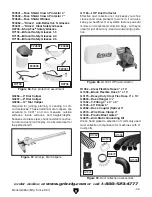
Страница 34: ...ong a spiral pattern they are also at an angle so that the shearing action leaves a glassy smooth cut on the toughest of woods Each cutterhead comes with 5 extra replacement inserts Figure 53 H7764 Byrd Shelix Cutterhead Figure 54 Recommended products for protect ing unpainted cast iron steel part on machinery G5562 SLIPIT 1 Qt Gel G5563 SLIPIT 12 oz Spray G2871 Boeshield T 9 12 oz Spray G2870 Boe...

Страница 35: ...G1163 1HP dust collector H1052 Clear Flexible Hose 4 x 10 G1536 Black Flexible Hose 4 x 10 G3179 Heavy Duty Clear Flex Hose 4 x 10 G8830 Hose Hanger 41 2 G1552 Y Fitting 4 x 4 x 4 G1545 90 Elbow 4 G2482 Hose Coupler Splice 4 G2974 Wire Hose Clamp 4 G1843 Plastic Blast Gate 4 G4679 Anti Static Grounding Kit We ve hand picked a selection of commonly used dust collection components for machines with ...

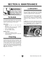
Страница 36: ...reful not to over lubricate them Large amounts of lubricant will attract sawdust causing the metal components to gum up and bind Figure 60 Leadscrew lubrication location Leadscrew Lubricate the outfeed table leadscrew with light machine oil as needed See the location shown in Figure 60 and Part 41 on Page 46 Wipe off excess oil and sawdust with a cloth Lubrication Vacuum excess wood chips and sawd...

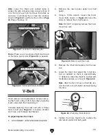
Страница 37: ... remove the motor mount hex nuts Figure 63 Motor mount hex nuts 4 Remove the V belt and replace it with a new one 5 Lower the motor and adjust the V belt ten sion as needed so there is approximately 1 4 deflection when the V belt is pushed with moderate pressure as shown in Figure 64 Note After the first 16 hours of belt life ten sion the belt as it will stretch and seat during this time Figure 64...

Страница 38: ...t 6 Motor bearings are at fault 7 Machine is undersized for the task 8 Motor has overheated 9 Motor is at fault 10 Centrifugal switch is at fault 1 Only cut wood products make sure moisture content is below 20 and there are no foreign materials in the workpiece 2 Replace bad V belt align pulleys and re tension 3 Correct motor wiring connections 4 Test for good contacts correct the wiring 5 Replace...

Страница 39: ...nt or surface wetness 2 Dull knives 1 Check to make sure moisture content is less than 20 and allow to dry if moisture is too high 2 Sharpen or replace knives Page 38 Long lines or ridges that run along the length of the board 1 Nicked or chipped knives 1 Adjust one of the nicked knives sideways replace knives Page 38 Uneven cutter marks wavy sur face or chatter marks across the face of the board ...

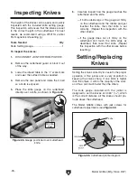
Страница 40: ...ully inspect how the gauge touches the cutterhead and the knife If both outside legs of the gauge sit firmly on the cutterhead and the middle pad just touches the knife then that knife is set correctly Repeat this inspection with the other knives If the gauge does not sit firmly on the cutterhead and touch the knife edge as described then reset that knife Repeat this inspection with the other kniv...

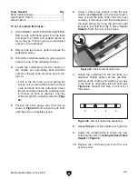
Страница 41: ...st Coat the knife and gib with a metal protectant Page 32 5 Position the knife gauge over the knife as shown in Figure 65 and loosen the gib bolts until the knife is completely loose Figure 67 Jack screw access hole 7 Rotate the cutterhead to the first knife you adjusted Slightly tighten all the gib bolts starting at the middle and working your way to the ends by alternating left and right see Fig...

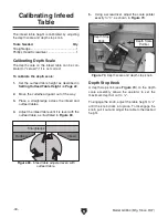
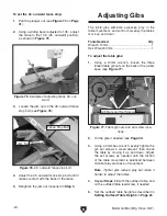
Страница 42: ...able can be cali brated or zeroed if it is not correct To calibrate the depth scale 1 Set the outfeed table height as described in Setting Outfeed Table Height on Page 22 2 Move the cutterhead guard out of the way 3 Place a straightedge across the infeed and outfeed tables 4 Adjust the infeed table until it is level with the outfeed table as illustrated in Figure 69 Depth Stop Knob A depth stop kn...

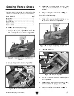
Страница 43: ...ten the jam nut loosened in Step 2 Figure 72 45 inward fence stop bolt Setting Fence Stops To set the 90 fence stop 1 Using a 90 square adjust the fence to the 90 position as shown in Figure 73 3 Loosen the jam nut on the 90 fence stop bolt see Figure 74 4 Adjust the 90 fence stop bolt until it makes contact with the 90 plunger knob shaft 5 Retighten the jam nut loosened in Step 3 Figure 71 Exampl...

Страница 44: ...e back of the jointer base see Figure 77 2 Oil the gibs if needed see Page 34 3 Using a 3mm hex wrench evenly tighten the gib set screws a small amount then check the table by moving it up and down Adjust the set screws as needed until the friction of the table movement is balanced between minimal play and ease of movement Note Tighter gibs reduce play but make it harder to adjust the tables 4 Rep...

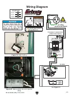
Страница 45: ...r 200MFD 125VAC The motor wiring shown here is current at the time of printing but it may not match your machine Always use the wiring diagram inside the motor junction box Ground Neutral Hot Ground 110 VAC 5 15 Plug As Recommended 5 1 2 8 3 Wiring Diagram Figure 78 Switch wiring See Figure 78 See Figure 79 Figure 79 Motor junction box and capacitor wiring ...

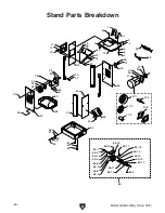
Страница 46: ...0 19 22 21 18 32 25 36 23 39 24 14 37 38 61 62 45 26 43 46 10 44 28 33 27 31 34 40 41 29 35 63 65 52 7 6 42 57 56 58 59 60 64 53 65 1 65 2 65 3 65 4 65 5 65 6 65 7 65 8 65 9 65 10 65 11 65 12 65 13 65 14 65 15 65 16 65 17 65 18 65 19 47 2 47 1 47 3 47 4 47 5 Stand Parts Breakdown ...

Страница 47: ...OLT 3 8 16 X 1 21 PW03M FLAT WASHER 6MM 62 PN08 HEX NUT 3 8 16 22 PN01M HEX NUT M6 1 63 P0654063 LEVELING FOOT 23 PW03M FLAT WASHER 6MM 64 P0654064 MOBILE BASE CHASSIS 24 PN01M HEX NUT M6 1 65 P0654065 PEDAL ASSEMBLY 25 P0654025 STRAIN RELIEF 6N 4 65 1 PEC10M E CLIP 9MM 26 P0654026 SWITCH BOX 65 2 P0654065 2 SPECIAL BOLT 27 P0654027 STRAIN RELIEF 6N 4 65 3 P0654065 3 SPECIAL FLAT WASHER 28 PFS03 F...

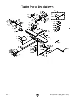
Страница 48: ... 118 119 120 121 122 123 124 125 126 127 128 129 130 131 133 134 135 136 137 138 139 140 141 143 144 145 147 148 149 150 151 152 153 154 155 156 157 158 161 162 163 164 165 166 167 168 168 169 170 172 176 177 179 180 181 182 184 187 188 189 190 191 192 193 195 1 195 195 2 195 3 Table Parts Breakdown ...

Страница 49: ...ER 10MM 166 PSB11M CAP SCREW M8 1 25 X 16 120 PB01M HEX BOLT M10 1 5 X 30 167 PLW04M LOCK WASHER 8MM 121 PRP39M ROLL PIN 4 X 20 168 PEC07M E CLIP 7MM 122 P0654122 SPECIAL KEY 9 5 X 9 5 X 128 169 P0654169 LINK 123 P0654123 LOCK SCREW ASSEMBLY 170 P0654170 SPECIAL BOLT 124 PN01M HEX NUT M6 1 172 P0654172 JOINTER TABLE ASSEMBLY 125 PSS12M SET SCREW M6 1 X 25 176 PN09M HEX NUT M12 1 75 126 P0654126 GI...

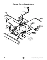
Страница 50: ...48 Model G0654 Mfg Since 9 07 211 234 230 231 232 233 229 228 212 214 213 205 206 207 208 209 210 201 204 203 238 217 216 215 218 219 221 220 222 223 224 227 236 235 237 239 226 225 Fence Parts Breakdown ...

Страница 51: ...9 PW06M FLAT WASHER 12MM 228 PS14M PHLP HD SCR M6 1 X 12 210 P0654210 SPECIAL NUT M12 229 PW03M FLAT WASHER 6MM 211 P0654211 FENCE SLIDE BRACKET 230 P0654230 REAR GUARD BASE 212 PSS04M SET SCREW M6 1 X 12 231 P0654231 REAR GUARD TOP 213 PN03M HEX NUT M8 1 25 232 PN35M ACORN NUT M6 1 214 PB26M HEX BOLT M8 1 25 X 30 233 PW03M FLAT WASHER 6MM 215 P0654215 BRACKET 234 P0654234 EXTENSION SPRING 216 PSB...

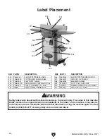
Страница 52: ...o order new labels Label Placement 300 301 302 303 304 305 306 307 308 309 310 REF PART DESCRIPTION REF PART DESCRIPTION 300 P0654300 FENCE CUTTERHEAD LABEL 306 P0654306 EAR PROTECTION RESPIRATOR 301 PLABEL 29 CUTTERHEAD GUARD LABEL 307 P0654307 UNPLUG 110V POWER 302 PLABEL 14 ELECTRICITY LABEL 308 P0654308 MACHINE ID LABEL 303 PLABEL 12A READ MANUAL VERTICAL NS 7 05 309 PPAINT 11 PUTTY TOUCH UP P...

Страница 53: ... metalworker ____ 0 2 Years ____ 2 8 Years ____ 8 20 Years ____20 Years 6 How many of your machines or tools are Grizzly ____ 0 2 ____ 3 5 ____ 6 9 ____10 7 Do you think your machine represents a good value _____Yes _____No 8 Would you recommend Grizzly Industrial to a friend _____Yes _____No 9 Would you allow us to use your name as a reference for Grizzly customers in your area Note We never use ...

Страница 54: ...D LINE FOLD ALONG DOTTED LINE GRIZZLY INDUSTRIAL INC P O BOX 2069 BELLINGHAM WA 98227 2069 Place Stamp Here Name_______________________________ Street_______________________________ City______________State______Zip______ Send a Grizzly Catalog to a friend ...

Страница 55: ...e tried in the State of Washington County of Whatcom We shall in no event be liable for death injuries to persons or property or for incidental contingent special or consequential damages arising from the use of our products To take advantage of this warranty contact us by mail or phone and give us all the details We will then issue you a Return Number which must be clearly posted on the outside a...

Страница 56: ......
Отзывы: