Grizzly G0580 Скачать руководство пользователя страница 18

-16-

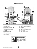
Model G0580 (Mfd. Since 11/06)

Site Considerations

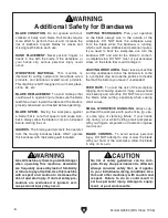
Figure 9. Minimum working clearances.

27"

26"


Weight Load

Refer to the 

Machine Data Sheet for the weight 

of your machine. Make sure that the surface upon 
which the machine is placed will bear the weight 
of the machine, additional equipment that may be 
installed on the machine, and the heaviest work-
piece that will be used. Additionally, consider the 
weight  of  the  operator  and  any  dynamic  loading 
that may occur when operating the machine.

Space Allocation

Consider  the  largest  size  of  workpiece  that  will 
be  processed  through  this  machine  and  provide 
enough space around the machine for adequate 
operator  material  handling  or  the  installation  of 
auxiliary equipment. With permanent installations, 
leave enough space around the machine to open 
or remove doors/covers as required by the main-
tenance  and  service  described  in  this  manual. 

See below for required space allocation.

Physical Environment

The  physical  environment  where  the  machine  is 
operated is important for safe operation and lon-
gevity  of  machine  components.  For  best  results, 
operate this machine in a dry environment that is 
free  from  excessive  moisture,  hazardous  chemi-
cals,  airborne  abrasives,  or  extreme  conditions. 
Extreme conditions for this type of machinery are 
generally  those  where  the  ambient  temperature 
range  exceeds  41°–104°F;  the  relative  humidity 
range  exceeds  20%–95%  (non-condensing);  or 
the  environment  is  subject  to  vibration,  shocks, 
or bumps.

Electrical Installation

Place this machine near an existing power source. 
Make  sure  all  power  cords  are  protected  from 
traffic, material handling, moisture, chemicals, or 
other hazards. Make sure to leave enough space 
around  machine  to  disconnect  power  supply  or 
apply a lockout/tagout device, if required.

Lighting

Lighting  around  the  machine  must  be  adequate 
enough that operations can be performed safely. 
Shadows, glare, or strobe effects that may distract 
or impede the operator must be eliminated.

Children or untrained people 

may be seriously injured by 

this machine. Only install in an 

access restricted location.

Содержание G0580

Страница 1: ...manufactured since 11 06 COPYRIGHT AUGUST 2004 BY GRIZZLY INDUSTRIAL INC REVISED MARCH 2015 BL WARNING NO PORTION OF THIS MANUAL MAY BE REPRODUCED IN ANY SHAPE OR FORM WITHOUT THE WRITTEN APPROVAL OF...

Страница 2: ...g grinding tool integrity and the usage of personal protective equipment The manufacturer will not be held liable for injury or property damage from negligence improper training machine modifications...

Страница 3: ...t Bearings 26 Adjusting Blade Guides 27 Calibrating Table Tilt Scale 28 Aligning Table 29 Aligning Fence 29 Miter Gauge 30 SECTION 4 OPERATIONS 31 Operation Overview 31 Disabling Switch 32 Workpiece I...

Страница 4: ...infor mation helps us determine if updated documenta tion is available for your machine Manufacture Date Serial Number Manual Accuracy We stand behind our machines If you have any questions or need h...

Страница 5: ...Cover I Fence Lock Knob J Front Table Lock Knob K Stand Assembly L Blade Tension Adjustment Knob M Guide Post N Guide Post Lock Knob O Blade Tension Scale P Blade Tracking Adjustment Knob Q Table Ins...

Страница 6: ...x Height 45 x 20 x 15 in Must Ship Upright Yes Electrical Power Requirement 115V or 230V Single Phase 60 Hz Prewired Voltage 115V Full Load Current Rating 9A at 115V 4 5A at 230V Minimum Circuit Size...

Страница 7: ...e Included Yes Construction Materials Table Precision Ground Cast Iron Trunnion Aluminum Fence Aluminum Base Stand Pre Formed Steel Frame Body Cast Iron Wheels Computer Balanced Cast Aluminum Tire Rub...

Страница 8: ...of DANGEROUS ENVIRONMENTS Do not use machinery in areas that are wet cluttered or have poor lighting Operating machinery in these areas greatly increases the risk of accidents and injury MENTAL ALERTN...

Страница 9: ...duce accidental contact with moving parts or flying debris Make sure they are properly installed undamaged and working correctly FORCING MACHINERY Do not force machine It will do the job safer and bet...

Страница 10: ...e bandsaw OFF and wait for the blade to come to a complete stop DO NOT twist or put excessive stress on the blade that could damage it LEAVING WORK AREA Never leave a machine running unattended Allow...

Страница 11: ...g operation and make sure it is connected to a power supply circuit that meets the specified circuit requirements For your own safety and protection of property consult an electrician if you are unsur...

Страница 12: ...ize requirements Minimum Gauge Size 14 AWG Maximum Length Shorter is Better 50 ft Grounding Requirements This machine MUST be grounded In the event of certain malfunctions or breakdowns grounding redu...

Страница 13: ...t come loose Neutral Hot Ground 110 VAC 5 15 Plug Pre wired Rewired for 220V Motor Rewired for 220V Ground 4 2 1 3 Rewired for 220V Start Capacitor 200MFD 125VAC Run Capacitor 25MFD 250VAC 5 Close and...

Страница 14: ...freight claim can be difficult When you are completely satisfied with the condi tion of your shipment inventory the contents Unpacking SUFFOCATION HAZARD Keep children and pets away from plastic bags...

Страница 15: ...Model G0580 Mfd Since 11 06 13 Hardware Recognition Chart...

Страница 16: ...eg Braces Sides 2 J Body Support Braces 2 K Saw Blade 1 L Hardware Bag 1 1 Carriage Bolts M8 1 25 x 16 34 Flange Nuts M8 1 25 34 M Hardware Bag 2 1 Upper Guide Assembly 1 Lower Guide Assembly 1 Blade...

Страница 17: ...c paint scraper optional Basic steps for removing rust preventative 1 Put on safety glasses 2 Coat the rust preventative with a liberal amount of cleaner degreaser then let it soak for 5 10 minutes 3...

Страница 18: ...onment The physical environment where the machine is operated is important for safe operation and lon gevity of machine components For best results operate this machine in a dry environment that is fr...

Страница 19: ...e base plate making sure the hole patterns match and are properly aligned 4 Insert a carriage bolt through two end holes in each brace and loosely secure them as shown in Figure 10 Assembling Stand Co...

Страница 20: ...ic cord clamp see Figure 12 and an M5 8 x 12 Phillips head screw 5 Attach the switch to the body with the two pre installed M5 8 x 16 Phillips head screws then ground the switch with the M5 8 x 12 Phi...

Страница 21: ...20 hex bolts and 6mm flat washers as shown in Figure 15 Installing Blade Guides Figure 15 Installing lower blade guide assembly Lower Guard Lower Guide Assembly To install the upper blade guide assem...

Страница 22: ...the bottom of each trunnion see Figure 22 Figure 22 Securing trunnion to support bracket Trunnions Knob Hex Bolt Figure 21 Table insert and pin Insert Pin 4 Remove the table pin and table insert show...

Страница 23: ...mm 7 Flat Washer 6mm 7 Knob M10 1 5 x 25 1 Tools Needed Qty Wrench 10mm 1 To install the fence 1 Secure the rear rail against the rear of the table with the flat un drilled surface facing up using two...

Страница 24: ...le tilt knobs Figure 25 Example of attached dust hose Dust Collection DO NOT operate this bandsaw without an ade quate dust collection system This bandsaw creates substantial amounts of wood dust whil...

Страница 25: ...wheel known as center tracking and the align ment of both wheels coplanar tracking The wheels on this bandsaw were aligned at the factory so center tracking is the only adjustment that needs to be pe...

Страница 26: ...ing 1 The motor powers up and runs correctly and 2 the safety disabling mechanism on the switch works correctly If during the test run you cannot easily locate the source of an unusual noise or vibrat...

Страница 27: ...hen you see the bandsaw blade start to flutter stop decreas ing the tension 6 Now slowly increase the tension until the blade stops fluttering then tighten the tension another quarter turn 7 Look at w...

Страница 28: ...ourself with the support bearing controls shown in Figure 32 4 Loosen the assembly lock bolt Support Bearing Lock Bolt Assembly Lock Bolt Support Bearing 6 Tighten the assembly lock bolt 7 Loosen the...

Страница 29: ...con trols shown in Figure 36 Adjusting Blade Guides Note For a quick gauge fold a dollar bill in half twice four thicknesses of a dollar bill is approximately 0 016 and place it between the support b...

Страница 30: ...of the blocks 0 004 away from the blade Note 0 004 is approximately the thickness of a piece of paper 9 Tighten the thumbscrews Whenever changing a blade or adjusting tension and tracking the upper an...

Страница 31: ...and the miter slot The distance you measure should be the same at both the front and the back of the table 6 Adjust the table as needed for proper align ment 7 Tighten the trunnion bolts Note Refer to...

Страница 32: ...s square with one edge against the face of the miter gauge and the other against the blade face as shown in Figure 40 Figure 40 Squaring miter gauge to blade Miter Gauge 2 Loosen the lock knob on the...

Страница 33: ...OMMEND that you read books review industry trade magazines or get formal training before beginning any projects Regardless of the content in this section Grizzly Industrial will not be held liable for...

Страница 34: ...mely fine dust and may reduce the life of the bearings This machine is NOT designed to cut metal glass stone tile etc cutting these materials with a table saw may lead to injury Foreign Objects Nails...

Страница 35: ...es are adjusted correctly 2 Loosen the guide post lock knob shown in Figure 42 3 Raise lower the guide post to within 1 from the top of the workpiece to the bottom of the blade guide assembly 4 Lock t...

Страница 36: ...Radius Figure 44 Recommended cutting radius per blade width Blade Dimensions Length Range 921 2 931 2 Width Range 1 8 3 4 Straight Cutting Use the largest width blade that you own Large blades excel a...

Страница 37: ...ough the cutting material with much more resistance than clean blades This extra resistance also causes unnecessary heat Resin pitch cleaners are excellent for cleaning dirty blades Blade Breakage Man...

Страница 38: ...through the slot in the table 1 Slide the blade through the table slot ensur ing that the teeth are pointing down toward the table Note If the teeth will not point downward in any orientation the blad...

Страница 39: ...uidance Ripping means cutting with the grain of the wood stock For plywood and other processed wood ripping simply means cutting down the length of the workpiece To make a rip cut 1 Adjust the fence t...

Страница 40: ...iter gauge Resawing means cutting the thickness of a board into two or more thinner boards see the fig ure below for an example The maximum board width that can be resawn is limited by the maxi mum cu...

Страница 41: ...rate too fast and a blade with too many TPI Cutting Curves When cutting curves simultaneously feed and turn the stock carefully so that the blade follows the layout line without twisting Use either a...

Страница 42: ...eces together in a manner that will not interfere with the cutting Hot glue on the edges works well as do brad nails through the waste portion Be careful not to cut into the brads or you may break the...

Страница 43: ...25 G5167 931 2 1 2 4 Hook 0 025 G5168 931 2 1 2 6 Hook 0 025 G5169 931 2 1 2 10 Raker 0 025 G5170 931 2 1 2 14 Raker 0 025 G5171 931 2 3 4 3 Hook 0 025 G5172 931 2 3 4 6 Hook 0 025 G5173 931 2 3 4 10...

Страница 44: ...f use dust collectors Model G1163P Model G0710 T10117 Big Mouth Dust Hood with Stand Capture dust from any machine operation with this Big Mouth Dust Hood Simply attach a 4 dust collection hose and ad...

Страница 45: ...a dry cloth If any resin has built up use a resin dissolving cleaner to remove it Protect the unpainted cast iron surfaces on the table by wiping the table clean after every use this ensures moisture...

Страница 46: ...At that point redressing will no longer be effective and the rubber tires must be replaced Redressing Rubber Tires To redress the rubber tires 1 DISCONNECT BANDSAW FROM POWER 2 Put on heavy leather gl...

Страница 47: ...kpiece material 2 Feed rate too fast for task 3 V belt slipping 4 Motor connection is wired incorrectly 5 Plug receptacle is at fault 6 Motor bearings are at fault 7 Motor has overheated 8 Motor is at...

Страница 48: ...ection system 1 Clean out dust port 2 Three options Check dust lines for leaks or clogs Move dust collector closer to saw Install a more powerful dust collector Blade wanders or doesn t cut straight 1...

Страница 49: ...re to it between the pulleys see the illustration in the following figure If the V belt is not properly tensioned perform the following Tensioning V Belt procedure Pulley Deflection Pulley Figure 57 C...

Страница 50: ...the V belt off the pulleys 6 Unthread the wheel mount bolt clockwise left hand thread and remove it and the flat washer from the wheel hub 7 Taking care not to misplace the shaft key slide the wheel f...

Страница 51: ...oplanar tracking Bringing the wheel into alignment may require a combination of shimming a wheel and center lateral tracking the upper blade Tools Needed Qty Straightedge 4 ft 1 Fine Ruler 1 Wrench or...

Страница 52: ...er rim on the other wheel In this case shim the wheel that does not touch the straightedge as instructed in the following Shimming a Wheel procedure If the wheels are not coplanar the straight edge wi...

Страница 53: ...hex nut that secures the upper wheel then slide the wheel from the shaft 4 Thread one set screw out and thread the other set screw in the same amount to tilt the wheel laterally For instance to tilt...

Страница 54: ...d draw a straight line parallel to the long edge 2 Slide the bandsaw fence out of the way and cut halfway through the board on the line by pushing it into the blade Turn the bandsaw OFF and wait for t...

Страница 55: ...t at the time of printing but may not match your machine If you find this to be the case use the wiring diagram inside the motor junction box CAPACITORS INVERTERS Some capacitors and power inverters s...

Страница 56: ...lug Pre wired 230 VAC 6 15 Plug As Recommended PADDLE SWITCH viewed from behind Motor Pre wired for 115V Ground 4 2 1 3 Start Capacitor 200M 125V Run Capacitor 25M 250V Motor Rewired for 230V Ground 4...

Страница 57: ...2 118 119 120 24 15 16 38 125 67 58 58 59 49 50 57 51 56 55 48 47 46 41 45 7 6 71 72 72 1 114 73 74 115 116 117 50 49 51 68 4 3 2 70 8 69 64 66 62 61 35 1 35 2 35 3 35 30 31 36 32 33 17 18 20 121 21 2...

Страница 58: ...69 P0580069 LOWER HINGE 16 P0580016 FLAT WASHER 4MM 70 P0580070 FLAT HD SCR M5 8 X 10 17 P0580017 SWITCH ENCLOSURE BRACKET 71 P0580071 HEX BOLT M8 1 25 X 35 18 P0580018 PHLP HD SCR M5 8 X 16 72 P0580...

Страница 59: ...10 P0580110 KNOB M10 1 5 118 P0580118 STEEL BALL 5 16 111 P0580111 HEX BOLT M10 1 5 X 50 119 P0580119 COMPRESSION SPRING 1 X 5 5 X 9 112 P0580112 HEX BOLT M8 1 25 X 80 120 P0580120 SET SCREW M10 1 5 X...

Страница 60: ...HEX BOLT M6 1 X 20 210 P0580210 FENCE SUPPORT SCREW M6 1 X 13 220 P0580220 HEX BOLT M6 1 X 10 211 P0580211 FENCE ADJUSTMENT SCREW Labels 134V2 138 139 141 142 143 144 145 146 REF PART DESCRIPTION REF...

Страница 61: ...metalworker ____ 0 2 Years ____ 2 8 Years ____ 8 20 Years ____20 Years 6 How many of your machines or tools are Grizzly ____ 0 2 ____ 3 5 ____ 6 9 ____10 7 Do you think your machine represents a good...

Страница 62: ...LINE FOLD ALONG DOTTED LINE GRIZZLY INDUSTRIAL INC P O BOX 2069 BELLINGHAM WA 98227 2069 Place Stamp Here Name_______________________________ Street_______________________________ City______________S...

Страница 63: ...shall be tried in the State of Washington County of Whatcom We shall in no event be liable for death injuries to persons or property or for incidental contingent special or consequential damages arisi...

Страница 64: ......

Отзывы: