9.2
On-the-fly Current or Speed Limit (V2.11 and later)
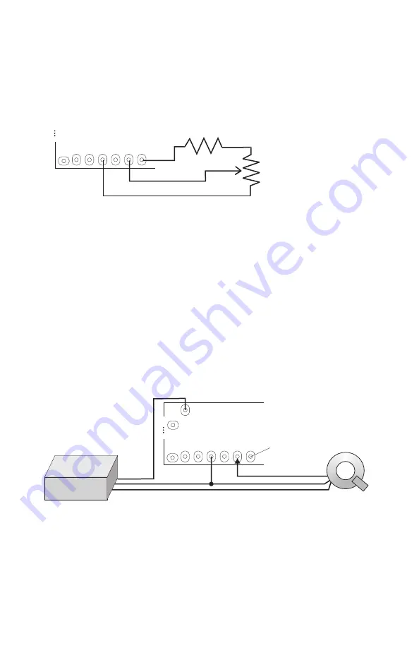
There are situations where it may be desirable to adjust the speed or
current limit of the Cycle Analyst without having to change the settings
in the setup menu. This can be accomplished by wiring a
potentiometer such that it sends a voltage signal to the
Vi
pad:
The optional resistor R2 is used to reduce the potentiometer wiper
range from 0-5V to just 0-3V so that the entire turn range is utilized. In
the advanced setup menu, you can select whether this voltage
regulates the current limit or the speed limit, and it will scale the limit
between 0 and the speed/current limit programmed in the setup menu.
9.3
Current Throttle or Cruise Control (V2.23 and later)
In other cases, it may be advantageous to use the Cycle Analyst to
directly regulate the motor controller rather than just limiting the power
via a throttle over-ride function. The example below shows how to wire
up a “current throttle”, such that the regular throttle signal is
intercepted by the Cycle Analyst, which takes this as the command
current. The Cycle Analyst then sends it’s own throttle signal along to
the motor controller.
In this manner, if full throttle is set to be 20 amps, then by riding half
throttle, you could ensure exactly 10 amps are drawn from the battery
regardless of the vehicle speed, giving the user more direct control
over their power usage. Similar setups can be used to implement
accurate cruise control systems. Note that it is essential to set the
AuxVoltage input (see
8.17
) to either the current or speed limit first,
otherwise the system will take off at full power when turned on.
19
(R2 2K7)
R1
5K Potentiometer
5V Throttle Power from Controller
Gnd
Throttle
Signal from Throttle
V+ G G Tx Vi 5V*
(CA PCB)
Th
Motor
Controller
Th Signal from CA
(Optional 5V
Throttle Power)
V+ G G Tx Vi 5V*
(CA PCB)


