Page 7
ReCal Md
Time 1yr
Alarm Md
Auto
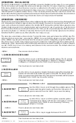
Use the <ROLL> key to set the ReCal mode timer to 1, 2 or 3 years. Press
<SAVE> to save the setting. This is used to set the CO sensor re-calibration
interval.
Use the <ROLL> key to set the alarm mode to auto or manual. The setting
controls how the relay alarms and the buzzer alarm resets back to normal mode.
For the auto setting, the device will reset the alarms automatically once the CO
level drops below the set alarm thresholds. For the manual setting, the CO level
must be below the alarm thresholds AND the user must press the TEST switch
on the device to reset the alarms. Press <SAVE> to save the setting.
21. RECAL TIMER
22. ALARM MODE
<MENU>
Press to advance to next menu item
<MENU>
Press to advance to next menu item
Only if
ReCal Mode
enabled
0 Filter
Enable
Display
CO Value
BackLite
Enable
Out Type
0-5 Vdc
Output
Test OFF
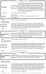
Use the <ROLL> key to enable or disable the zero filter. When enabled, the
device will filter low ppm readings such that 0-5 ppm CO will display and output
0 ppm. When disabled, 0-5 ppm will display and output actual 0-5 ppm. Press
<SAVE> to save the setting. Note that this should be set to disable when doing a
ZERO gas calibration.
Use the <ROLL> key to toggle the setting to either CO Value or Status. When set
to CO value, the actual ppm value of the CO reading will be displayed on the
LCD. When set to Status, the ppm value will not be displayed only the device
operating status. Press <SAVE> to save the setting.
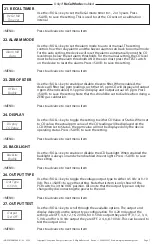
Use the <ROLL> key to enable or disable the LCD backlight. When enabled the
backlight is always on and when disabled it never lights. Press <SAVE> to save
the setting.
Use the <ROLL> key to toggle the voltage output type to either 0-5 Vdc or 0-10
Vdc. Press <SAVE> to save the setting. Note that is item is only shown if the
PCB switch is in the VOLT position. Also note that the output type can only be
changed by disconnecting the power to the unit.
Use the <ROLL> key to scroll through the available options. The output and
display depends on the output type configuration. For 4-20 mA output the
settings are OFF, 4, 8, 12, 16, 20 mA, for 0-5 Vdc output they are OFF, 0, 1, 2, 3, 4,
5, Vdc and for 0-10 Vdc output they are OFF, 2, 4, 6, 8, 10 Vdc. This can be used to
test the output sinal.
23. ZERO FILTER
24. DISPLAY
25. BACKLIGHT
26. OUTPUT TYPE
27. OUTPUT TEST
<MENU>
Press to advance to next menu item
<MENU>
Press to advance to next menu item
<MENU>
Press to advance to next menu item
<MENU>
Press to advance to next menu item
<MENU>
Press to advance to next menu item
IN-GE-CMD5B5XXX-01-02 03/19
Copyright © Greystone Energy Systems, Inc. All Rights Reserved Phone: +1 506 853 3057 Web: www.greystoneenergy.com


