background image

Page  1

INTRODUCTION

The CO Transmitter uses an electrochemical 

sensor to monitor the carbon monoxide level 

and outputs a field-selectable 4-20 mA or 

voltage signal. The voltage signal may also be set 

to 0-5 or 0-10 Vdc. The sensing range and output 

may be scaled to either 100, 150, 300, 400 or 500 

ppm via the on-board menu. A front panel LCD 

is standard to ensure easy setup and operation.

Other standard features include a back light 

for the LCD, a front panel test switch, status 

indication and an alarm buzzer. The test function 

may also be controlled remotely with a digital 

input signal. A three-key menu is implemented to allow local configuration of all device parameters.

BEFORE INSTALLATION

Read these instructions carefully before installing and commissioning the CO Transmitter. Failure to follow 

these instructions may result in product damage. Do not use in an explosive or hazardous environment, 

with combustible or flammable gases, as a safety or emergency stop device or in any other application 

where failure of the product could result in personal injury.

 Take electrostatic discharge precautions 

during installation and do not exceed the device ratings.

MOUNTING

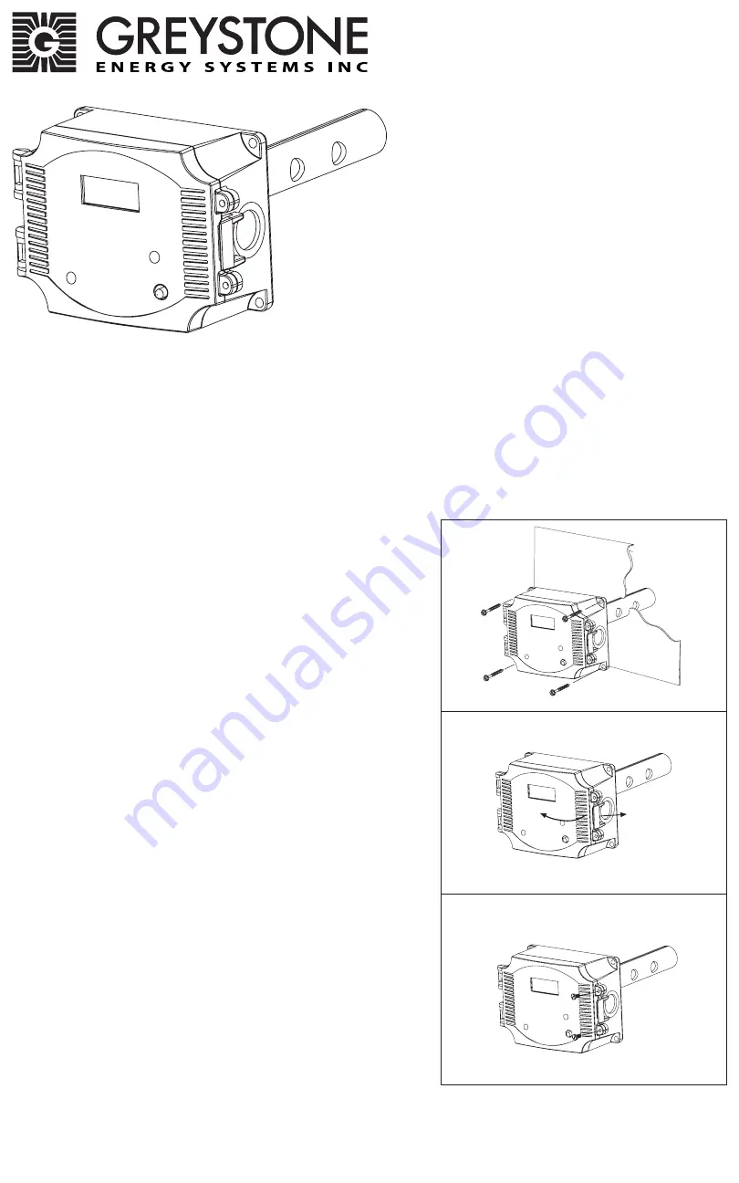
The CO duct type sensor installs on the outside of a return 

air duct with the sampling tube inserted into the duct. Use 

the included foam plug to prevent air from entering the 

enclosure through the conduit and causing an incorrect 

reading. Mount the sensor in an easily accessible location 

in a straight section of duct at least five feet from corners 

and other items that may cause disturbances in the air flow. 

Avoid areas with vibrations or rapid temperature changes.

The duct CO detector principal of operation is based on the 

Venturi effect of the probe that extends into the HVAC duct. 

Air flowing through the duct is forced into the vent holes on 

one side of the probe, into the enclosure, over the CO sensor 

and then is drawn back out of the enclosure via the probe 

vent holes on the opposite side.

Drill or punch a 1-1/8” or 1-1/4” hole in the duct at the 

preferred location and insert the probe into the hole to mark 

the enclosure mounting holes. Remove the unit and drill the 

four mounting holes. Clean all drilled holes of debris before 

mounting the device. Mount the enclosure to the duct with 

four sheet metal screws such that the duct air flow is parallel 

with the vent holes in the probe (i.e.: air flows directly into 

the probe holes). To prevent air leaks, ensure the gasket is 

compressed around the probe between the device enclosure 

and the air duct.

Open the cover by releasing the latch and connect the device 

according to the wiring instructions. After wiring and setup 

are complete, close and latch the cover. Secure it with two 

self-tapping screws in the holes provided. 

HARDWARE SETUP

The only hardware setup required is to select the analog 

output type with the PCB switch labeled VOLT and mA. Slide 

the switch to the correct position for the required output 

signal type, either 4-20 mA or 0-5/10 Vdc.

Figure 1

Figure 3

Figure 2

IN-GE-CMD5B5XXX-01-02     03/19

Copyright © Greystone Energy Systems, Inc.   All Rights Reserved    Phone:  +1 506 853 3057  Web: www.greystoneenergy.com

Carbon Monoxide Transmitter

CMD5B5 Series - Installation Instructions

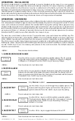
Содержание CMD5B5 Series

Страница 1: ...ve feet from corners and other items that may cause disturbances in the air flow Avoid areas with vibrations or rapid temperature changes The duct CO detector principal of operation is based on the Venturi effect of the probe that extends into the HVAC duct Air flowing through the duct is forced into the vent holes on one side of the probe into the enclosure over the CO sensor and then is drawn ba...

Страница 2: ...power is applied The current signal has a maximum load that it will drive and the voltage output has a minimum load Follow the ratings in the Specification section or inaccurate readings may result The power must be disconnected to change from VOLT to mA The analog output CO signal is typically connected directly to the Building Automation System BAS and used as a control parameter or for logging ...

Страница 3: ...eset to Normal Mode when the CO level drops below the trip level hysteresis value In order to reset the relay alarms to Normal Mode the user must also press theTEST switch on the front cover or activate the remote TEST input If the CO level is below the alarm level AND the TEST switch is pressed then the relay alarms will return to the Normal Mode The Manual Reset also applies to the buzzer alarm ...

Страница 4: ... device network address the installer MUST change the settings before operation Any changes made are saved in non volatile memory and are restored in case of a power loss Only the menu items relevant to the device model will be shown The menu can be accessed at any time after the warm up mode and if there is 5 minutes of inactivity the menu will close and normal operation will continue Note that t...

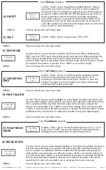
Страница 5: ...used for Fail Safe operation as the relay will change state on power loss Press SAVE to save the setting Use the ROLL key to toggle relay 1 ON or OFF MENU Press to advance to next menu item MENU Press to advance to next menu item MENU Press to advance to next menu item 7 HYSTERESIS 8 DELAY 9 DIRECT 10 TEST Only if Relay 1 installed MENU Press to advance to next menu item Only if Relay 2 installed ...

Страница 6: ...when the TEST switch is pressed Use the ROLL key to enable disable or reset When disabled the device will not sound the buzzer or provide LCD and status LED indication when the sensor life is exceeded When enabled the fault alarm will activate to indicate the sensor life is exceeded Press SAVE to save the setting If it is set to reset and SAVE is pressed then the fault condition is cleared the lif...

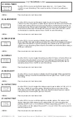
Страница 7: ...he setting to either CO Value or Status When set to CO value the actual ppm value of the CO reading will be displayed on the LCD When set to Status the ppm value will not be displayed only the device operating status Press SAVE to save the setting Use the ROLL key to enable or disable the LCD backlight When enabled the backlight is always on and when disabled it never lights Press SAVE to save the...

Страница 8: ... on the cover as before The sensor must be continuously powered for at least 1 2 hour prior to calibration Calibrate the sensor first in clean air with no CO gas present Simply adjust the ZERO pot on the sensor board until 4 mA or 0 Vdc output is obtained and the LCD displays 0 ppm Note that the 0 Filter menu item should be disabled to set the 0 ppm The ZERO and SPAN pots are located on the edge o...

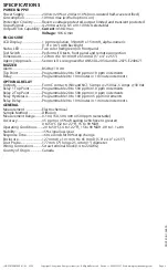
Страница 9: ...1 minute increments OPTIONAL RELAY Outputs Form C contacts NO and NC 5 Amps 250 Vac 5 Amps 30 Vdc Relay 1 Trip Point Programmable 20 to 500 ppm in 10 ppm increments Relay 2 Trip Point Programmable 20 to 500 ppm in 10 ppm increments Relay Hysteresis Programmable 10 to 100 ppm in 5 ppm increments Relay Delay Programmable 0 to 10 minutes in 1 minute increments GENERAL Measurement Electrochemical Samp...

Отзывы: