background image

FumeJet

®

 Fume Exhaust Fans

7

®

Move the fan to the desired location. Check and tighten 
fasteners throughout the unit and then fasten securely 
through mounting holes provided in the base angles. 
The unit must be set level (shimming may be necessary). 
Flexible duct connections and vibration isolators should 
be used where noise is a factor.

The motor voltage and ampere rating must be checked 
for compatibility with the electrical supply prior to final 
electrical connection. Supply wiring to the fan must 
be properly fused, and conform to local and national 
electrical codes.

IMPORTANT

When installing a fan, ensure the proper protective 
devices are used to protect personnel from moving 
parts and other hazards.

Electrical Disconnects

All fan motors should have disconnects located in 
close visual proximity to turn off electrical service. 
Service disconnects shall be locked out when 
maintenance is being performed.

Moving Parts

All moving parts must have guards to protect 
personnel. Refer to local codes for requirements as to 
the number, type and design. Fully secure fan wheel 
before performing any maintenance. The fan wheel 
may start “free wheeling” even if all electrical power 
has been disconnected. Before the initial start-up 
or any restart, check the guards (motor cover and 
weatherhood) and check the access doors to ensure 
that they are installed and secure.

Installation

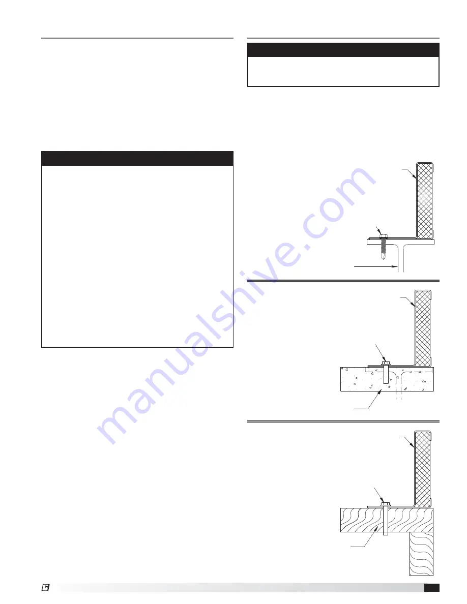
Roof Curb and Mounting Details

Required with curb cap inlet box or mega stack. 

The 

figures below illustrate three common methods used 
to install roof curbs for FumeJet

®

 systems. Methods 

used to attach a unit are dependent on local codes, roof 
construction design and roof construction materials. 
Consult an architect or structural engineer for proper 
means of attachment.

NOTE

Steel, concrete or wood roof support is per structural 
engineer and in accordance with load requirements 
and applicable building codes.

Steel

STEEL STRUCTURAL SUPPORT
(BY OTHERS, SEE NOTE ABOVE)

Continuous weld or stitch weld.
Minimum 6 inch 

(152.4 mm) 

stitch weld by 

3.25 inch 

(82.5 mm)

 spacing minimum. 

Minimum 6 inch 

(152.4 mm)

 weld on each corner.

OR

Install 5/16 inch 

(7.9375 mm)

 24 Dril-Flex® Self-Drilling

Tapping Screws. 3/16 inch 

(4.7625 mm) 

minimum thread 

engagement into A36 steel, centered in flange.
4.5 inch 

(114.3 mm) 

spacing

5/8 inch 

(15.875 mm) 

minimum edge distance

ALL HARDWARE BY OTHERS  

Greenheck Roof Curb GPFHL

Concrete

CONCRETE STRUCTURAL SUPPORT
(BY OTHERS, SEE NOTE ABOVE)

Install 3/8 inch 

(9.525 mm) 

SS power wedge bolts

2.5 inch 

(63.5 mm) 

maximum spacing from curb corners

4.5 inch 

(114.3 mm) 

maximum bolt spacing

3.5 inch 

(88.9 mm) 

minimum embedment

4.5 inch 

(114.3 mm) 

minimum edge

distance centered in flange
ALL HARDWARE BY OTHERS  

Greenheck Roof Curb GPFHL

Wood

WOODEN STRUCTURAL SUPPORT
(BY OTHERS, SEE NOTE ABOVE)

Greenheck Roof Curb GPFHL

Install 3/8 inch 

(9.525 mm)

 SS lag or thru-bolt with 

1 inch 

(25.4 mm) 

O.D. washer

2.5 inch 

(63.5 mm)

 maximum spacing from curb corners

4.5 inch 

(114.3 mm)

 maximum bolt spacing

3.5 inch 

(88.9 mm)

 minimum tread engagement, 

not including tapered tip
2 inch 

(50.8 mm) 

minimum edge distance, 

centered in flange
Pre-drill holes 40-60% of lag diameter
ALL HARDWARE BY OTHERS

Содержание FumeJet FJC-300

Страница 1: ...peut tre suffisamment chaud pour provoquer une douleur voire une blessure Laisser le moteur refroidir avant toute maintenance ATTENTION Faire preuve de pr caution dans les atmosph res explosives FJC 3...

Страница 2: ...phere which is sealed to prevent the entry of blowing dust rain or snow Temperatures should be evenly maintained between 30 to 110 F 1 to 43 C wide temperature swings may cause condensation and sweati...

Страница 3: ...m Storage 3 General Information Unit and System Identification Tags 4 Pre Installation Information 4 Electrical Disconnects 4 Moving Parts 4 Guards Motor Cover Weatherhood 4 Access Doors 4 Air Pressur...

Страница 4: ...ormation unique to the unit When contacting your local manufacturer s representative with future needs or questions please have the information on this label available Tags are mounted in an area whic...

Страница 5: ...t Installations Inlet Duct Turns Installation of a duct turn or elbow too close to the fan inlet reduces fan performance because air is loaded unevenly into the fan wheel To achieve full fan performan...

Страница 6: ...coating repair section of this manual for details involving touch up of damaged surfaces Lift unit before mounting the stack to the fan body Use standard lifting and rigging practices ALL lifting bra...

Страница 7: ...illustrate three common methods used to install roof curbs for FumeJet systems Methods used to attach a unit are dependent on local codes roof construction design and roof construction materials Consu...

Страница 8: ...installation of the duct drop Duct support will be supplied with roof curb from fan manufacturer or by others Duct Drop and Connection by others Duct Spacing FJC 300 FJI Duct Support inches mm 306 11...

Страница 9: ...ons with application appropriate sealant or tape Stack Installation NOTE Fans should never be lifted by the shaft motor motor cover or accessories Equipment Supports Model GESS equipment supports are...

Страница 10: ...closed Any increase in fan speed represents a substantial increase in load on the motor To avoid motor overheating and possible burnout motor load amperes should always be checked and compared to nam...

Страница 11: ...ening the inlet cone ring bolts and centering the cone ring on the wheel If additional adjustment is required to maintain a constant radial gap loosening the bearing bolts and centering the wheel is a...

Страница 12: ...for colors other than our standard TOUCH UP PAINT REPAIR KIT CONTENTS One pint of Kem Kromik primer including a technical data sheet One pint of industrial enamel including a technical data sheet Four...

Страница 13: ...ere the motor will run in either direction depending on how it has been wired To reverse rotation of a 3 phase motor interchange any two of the three electrical leads Single phase motors can be revers...

Страница 14: ...easing the upper limiting frequency Always check the fan rpm when adjusting the operating frequency Do not exceed maximum class fan rpm of the wheel Belt Span De ection Belt Span 64 Once the unit has...

Страница 15: ...ing to NLGI Grade 2 Factory recommends Mobilux EP 2 The use of synthetic lubricants will increase lubrication intervals by approximately 3 times In addition to lubricating the bearings at speci ed int...

Страница 16: ...cturers procedures for removal and installation 3 Before removing the bearing bolts make sure the shaft is supported slightly Remember to consider the wheel weight on the shaft 4 Remove both bearings...

Страница 17: ...make certain unit is not capable of operation during repairs CAUTION La pr sence d un moteur antid flagrant sur un ventilateur ne garantit pas que tout l appareil est antid flagrant Pour conna tre les...

Страница 18: ...ith optional curb cap inlet box and inlet flanges Stack Motor Cover Disconnect Switch Motor Plate Motor Integrated Mounting Rails Access Door Curb Cap Isolation Damper Roof Curb Scroll Housing Inlet C...

Страница 19: ...s in system Use correction factor to adjust for temperature altitude Resize ductwork Clean lters coils Change fan speed High Motor Amp Draw Fan Check rotation of wheel Reduce fan speed Duct System Res...

Страница 20: ..._____ AM PM Notes __________________________________________ ________________________________________________ ________________________________________________ _________________________________________...

Отзывы: