background image

32

Installation and Maintenance

Service Manual

9.2 Procedure of Troubleshooting

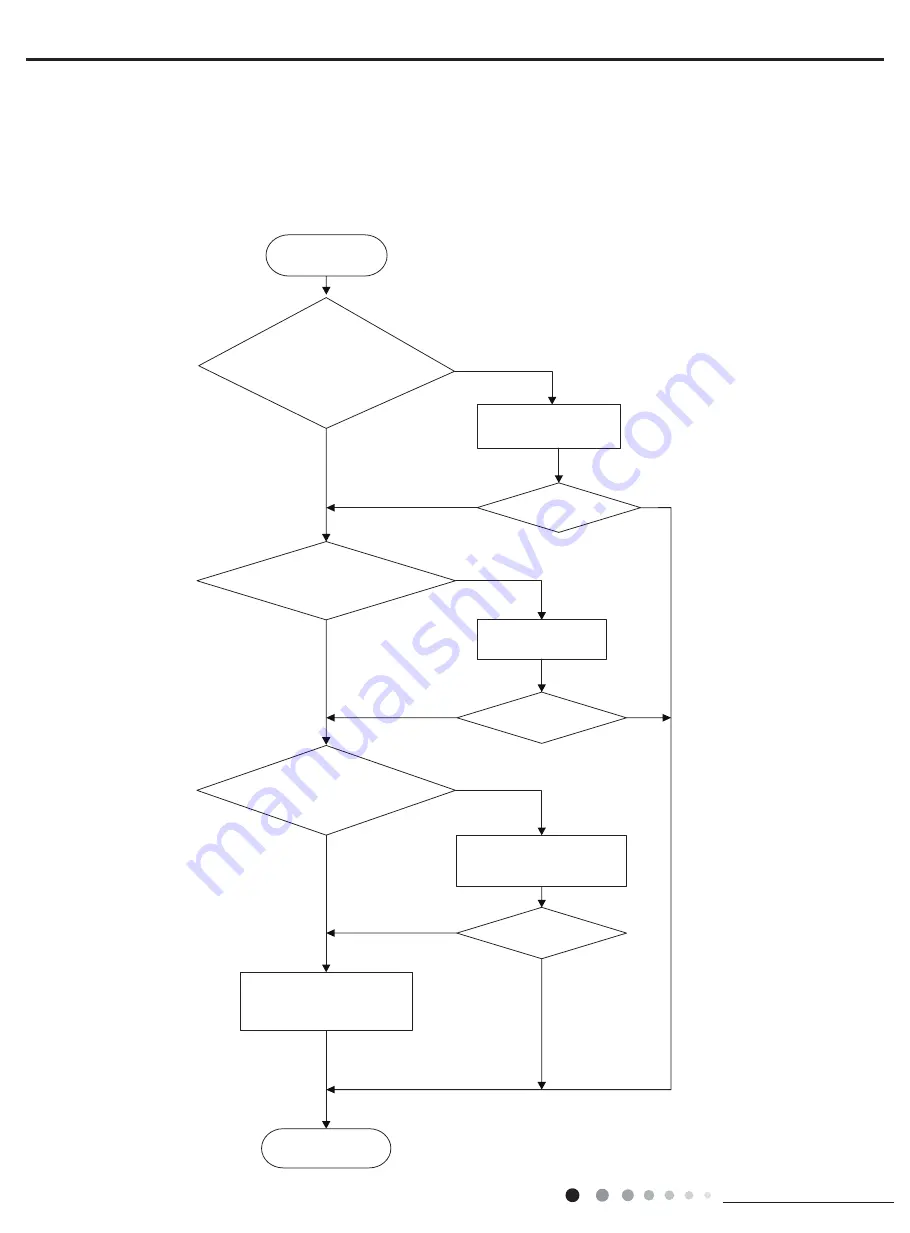
1. Malfunction of Temperature Sensor

Main detection points:

● Is the wiring terminal between the temperature sensor and the controller loosened or poorly contacted?
● Is there short circuit due to trip-over of the parts?
● Is the temperature sensor broken?
● Is mainboard broken?

Malfunction diagnosis process:

Is the wiring terminal between the 

temperature sensor and the controller 

loosened or poorly contacted?

Start

Insert the temperature 

sensor tightly

Yes

Yes

Yes

Yes

Yes

Yes

No

No

No

No

No

No

Is malfunction 

eliminated

Is malfunction 

eliminated

Is malfunction 

eliminated

Replace it with a 

temperature sensor with 

the same model

Make the parts upright

Is there short circuit due to trip-

over of the parts

Is the temperature sensor normal 

according to the resistance table?

Replace the mainboard with 

the same model.

End

Содержание GWH28AAE-K3NNA1A

Страница 1: ...GREE ELECTRIC APPLIANCES INC OF ZHUHAI Change for Life Service Manual Models GWH28AAE K3NNA1A GWH28AAE K3NNA2A Refrigerant R410A ...

Страница 2: ...ntrol 11 6 1 Remote Controller Introduction 11 6 2 Brief Description of Modes and Functions 14 Part Ⅱ Installation and Maintenance 19 7 Notes for Installation and Maintenance 19 8 Installation 22 8 1 Installation Dimension Diagram 22 8 2 Installation Parts checking 24 8 3 Selection of Installation Location 24 8 4 Electric Connection Requirement 24 8 5 Installation of Indoor Unit 24 8 6 Installatio...

Страница 3: ...1 Removal Procedure 49 11 1 Removal Procedure of Indoor Unit 49 11 2 Removal Procedure of Outdoor Unit 54 Appendix 59 Appendix 1 Reference Sheet of Celsius and Fahrenheit 59 Appendix 2 Configuration of Connection Pipe 59 Appendix 3 Pipe Expanding Method 60 Appendix 4 List of Resistance for Temperature Sensor 61 ...

Страница 4: ...1 Technical Information Service Manual 1 Summary Part Ⅰ Technical Information Indoor Unit GWH28AAE K3NNA1A I GWH28AAE K3NNA2A I Outdoor Unit GWH28AAE K3NNA1A O Remote Controller YAW1F1 ...

Страница 5: ... Indoor Unit Fan Type GWH28AAE K3NNA1A I GWH28AAE K3NNA2A I Product Code of Indoor Unit CA476N02101 CA477N01301 Fan Type Cross flow Diameter Length DXL mm Ф108X830 Fan Motor Cooling Speed SH H M L SL r min 1330 1200 1000 900 Fan Motor Heating Speed SH H M L SL r min 1330 1200 1000 900 Output of Fan Motor W 35 Fan Motor RLA A 0 35 Fan Motor Capacitor μF 3 Evaporator Form Aluminum Fin copper Tube Pi...

Страница 6: ...Fan Motor Speed rpm 850 Output of Fan Motor W 35 Fan Motor RLA A 0 8 Fan Motor Capacitor μF 4 5 Air Flow Volume of Outdoor Unit m3 h 1800 Fan Type Axial flow Fan Diameter mm Ф520 Defrosting Method Automatic Defrosting Climate Type T1 Isolation I Moisture Protection IPX4 Permissible Excessive Operating Pressure for the Discharge Side MPa 4 3 Permissible Excessive Operating Pressure for the Suction ...

Страница 7: ...pe connecting indoor and outdoor unit Inlet and outlet pipe temperature of heat exchanger Fan speed of indoor unit Fan speed of outdoor unit Indoor Outdoor P MPa T1 C T2 C 27 19 35 24 28K 0 9 1 1 in 6 8 out 10 12 in 75 85 out 37 43 Super High High Rated heating condition C DB WB Model Pressure of gas pipe connecting indoor and outdoor unit Inlet and outlet pipe temperature of heat exchanger Fan sp...

Страница 8: ...5 Technical Information Service Manual 3 Outline Dimension Diagram 3 1 Indoor Unit Unit mm Unit mm 3 2 Outdoor Unit 364 560 700 396 340 965 897 1080 245 324 79 154 43 207 685 188 Φ70 Φ70 43 ...

Страница 9: ...t Outdoor unit COOLING HEATING 4 Way valve COOLING Discharge Suction Heat exchanger evaporator Heat exchanger condenser Valve Valve Valve Liquid pipe side Gas pipe side Accumlator Compressor Strainer Strainer Strainer Capillary Capillary Connection pipe specification Liquid pipe 1 4 6mm Gas pipe 5 8 16mm ...

Страница 10: ...BU Blue Grounding wire YEGN Yellow Green BK Black VT Violet OG Orange Note Jumper cap is used to determine fan speed and the swing angle of horizontal lover for this model 6363247703 7 7 1 5 8 2 3 60 1 5 725 5 1 0 1 7 1 83 2 1 1 1 20 287 63 63 3 287 225 81 7 0 1 7 1 8 3 9 325 725 1 8 3 803 3 7 50 1 2 02725 6 1 8 6 1 211 7 1 63 2 5 5 9 5 1 35 17 5 8 7 2 5 63 67 33 1 78 5220 57 57 6 1625 7 03 6 1625...

Страница 11: ...ed with the unit 7 127 0RWRU JURXQG RQO DSSOLHV WR WKH LURQ VKHOO PRWRU 3 35 17 5 8 7 2 5 5 1 8 1 8 1 3 8 1 203 6 5 0 1 1 1 1 225 81 7 7 0 32 5 5 20 11 5 1 203 3 2 1 8 1 0 1 1 8 8 1 203 217 725 1 8 1 3 8 3 02725 3 3 3 1 1 2875220 33 1 8 33 97 9 9 1 97 9 9 3 28778 57 7 03 287 78 6 1625 75 16 250 5 7 75 287 75 1 7 50 1 2 3 3 35 6685 6 7 5 5 6 6725 6 1 ė Ė ...

Страница 12: ...cation wire 4 Fuse 5 Indoor fan driven capacitor 6 Neutral wire interface of cold plasma 7 Neutral wire interface of power supply 8 Interface of indoor fan 9 Live wire interface of cold plasma 10 Interface of up down swing motor 11 Interface of indoor fan feedback 12 Jumper cap 13 Interface of left right motor 14 Temperature sensor interface 2 3 4 5 6 7 8 9 10 11 12 13 14 1 ...

Страница 13: ...nsformer 6 Terminal for high pressure protection 7 Terminal for low pressure protection 8 Terminal for outdoor ambient temp sensor 9 Terminal for outdoor pipe temp sensor 10 Terminal for communication wire 11 Protective tube 12 Terminal for neutral wire 13 Terminal for live wire 14 Wiring terminal of outdoor discharge temperature sensor Only for the models with this function 15 Current mutual indu...

Страница 14: ...ignal has been sent to the air conditioner Under off status set temperature and clock icon will be displayed on the display of remote controller If timer on timer off and light functions are set the corresponding icons will be displayed on the display of remote controller at the same ime Under on status the display will show the corresponding set function icons 1 On Off button 2 Mode button 3 Fan ...

Страница 15: ...ture In AUTO mode set temperature is not adjustable When setting Timer On or Timer Off press or button to adjust the time Press this button in COOL or DRY mode to turn on X fan function When this function is started up indoor fan will still operate at low fan speed for a while after turning off the unit by remote controller Press this button to turn on the display s light and press this button aga...

Страница 16: ...TURBO buttons simultaneously for 10s remote controller will send WIFI reset code and then the WIFI function will be turned on WIFI function is defaulted ON after energization of the remote controller This function is only available for some models Press TEMP and TIMER simultaneously in HEAT mode to start 8 Heating Function Nixie tube on the remote controller displays and a selected temperature of ...

Страница 17: ...temperature is 20 Cooling and heating unit When Tamb 19 Tcompensation unit will be in heating mode Tpreset 20 Cooling only unit When Tamb 22 or 72 unit will be in fan mode Tpreset 25 For cooling and heating unit under condition that 19 Tcompensation Tamb 26 For cooling only unit under condition that 22 Tamb 26 when unit is initially turned on in auto mode it will operate according to auto fan mode...

Страница 18: ...nated For some models they can only be restated up after re energized Please refer to maintenance part for display information and disposal method for details 3 Drying mode Operation condition and process for drying mode When Tamb Tset 2 the system starts drying and cooling In this case the compressor and the ODU fan motor operate and the IDU fan motor operates at low speed When Tset 2 Tamb Tset 2...

Страница 19: ...tube is resumed normally the ODU fan motor resumes operation Noise silencing protection When turning off the unit or during mode switchover the 4 way valve is closed In order to decrease noise the 4 way valve will delay 2mins to be closed Overcurrent protection this protection function is not available for those models whose cooling capacity 12000Btu h During operation process if controller detect...

Страница 20: ...ation of turbo function the system operates at the maximum fan speed 5 Dry function Dry function can be set under cooling and drying modes During operation of drying function the fan will stop operation after operating for a period of time when turning off the unit 6 Auto fan speed control Auto fan speed control can be set under cooling heating and fan mode During operation of auto fan speed contr...

Страница 21: ...ilure when turning off the unit Memory content OFF status mode up down swing light set temperature set fan speed general timer Fahrenheit Celsius General timer can be memorized Time of timer is calculated again from energization Clock timer can t be memorized 4 Special Function 1 Health function for the model with health function During operation of the IDU fan motor press health button on the rem...

Страница 22: ...unit adequately grounded The grounding wire can t be used for other purposes 6 Must apply protective accessories such as protective boards cable cross loop and wire clip 7 The live wire neutral wire and grounding wire of power supply must be corresponding to the live wire neutral wire and grounding wire of the air conditioner 8 The power cord and power connection wires can t be pressed by hard obj...

Страница 23: ...ssure rise or compressor rupture resulting in injury 4 During refrigerant recovery make sure that liquid valve and gas valve are fully closed and power is disconnected before detaching the connection pipe If compressor starts running when stop valve is open and connection pipe is not yet connected air will be sucked in and cause pressure rise or compressor rupture resulting in injury 5 When instal...

Страница 24: ...ing tape 4 Electroprobe 7 Electronic leakage detector 10 Pipe pliers pipe cutter 2 Screw driver 5 Universal meter 8 Vacuum pump 11 Pipe expander pipe bender 3 Impact drill drill head electric drill 6 Torque wrench open end wrench inner hexagon spanner 9 Pressure meter 12 Soldering appliance refrigerant container ...

Страница 25: ...ipe Space to the wall Space to the obstruction Space to the obstruction Space to the obstruction At least 50cm At least 200cm At least 30cm At least 30cm At least 50cm Space to the ceiling Space to the wall At least 15cm At least 15cm At least 15cm At least 250cm Space to the wall o o l f e h t o t e c a p S A t l e a s t 3 0 0 c m ...

Страница 26: ...oor unit Make the bound pipes pass through the wall hole and then connect outdoor unit Neaten the pipes Vacuum pumping and leakage detection Check after installation and test operation Finish installation Note this flow is only for reference please find the more detailed installation steps in this section Select outdoor unit installation location Install the support of outdoor unit select it accor...

Страница 27: ... grounding with specialized grounding device by a professional Please make sure it is always grounded effectively otherwise it may cause electric shock 2 The yellow green wire in air conditioner is grounding wire which can t be used for other purposes 3 The grounding resistance should comply with national electric safety regulations 4 The appliance must be positioned so that the plug is accessible...

Страница 28: ...e on the wall slightly downward to the outdoor side with the gradient of 5 10 As show in Fig 2 Note Left Wall Φ70mm Right Mark in the middle of it Level meter Rear piping hole Wall Space to the wall above 150mm Space to the wall above 150mm Φ70mm Rear piping hole Insulating pipe Torque wrench Open end wrench Indoor pipe Pipe Union nut Union nut Pipe joint Pipe Hex nut diameter Tightening torque N ...

Страница 29: ...ly at the end 2 Make the power connection wire go through the cable cross hole at the back of indoor unit and then pull it out from the front side As show in Fig 12 3 Remove the wire clip connect the power connection wire to the wiring terminal according to the color tighten the screw and then fix the power connection wire with wire clip As show in Fig 13 Note Note Fig 11 Fig 12 Fig 13 Fig 14 Fig ...

Страница 30: ...ver As show in Fig 21 2 Remove the screw cap of valve and aim the pipe joint at the bellmouth of pipe As show in Fig 22 Fig 18 Fig 19 Fig 20 Fig 21 Fig 22 1 After tightening the screw pull the power cord slightly to check if it is firm 2 Never cut the power connection wire to prolong or shorten the distance Note 5 Connect Outdoor Electric Wire 1 Remove the wire clip connect the power connection wi...

Страница 31: ...valve and the nut of refrigerant charging vent 2 Connect the charging hose of piezometer to the refrigerant charging vent of gas valve and then connect the other charging hose to the vacuum pump 3 Open the piezometer completely and operate for 10 15min to check if the pressure of piezometer remains in 0 1MPa 4 Close the vacuum pump and maintain this status for 1 2min to check if the pressure of pi...

Страница 32: ...erminal of PG motor is not connected tightly 3 Fan blade rotates unsmoothly 4 Malfunction of motor 5 Main board is broken 4 Malfunction protection of jumper cap C5 Operation of remote controller or control panel is available but the unit won t act 1 There s not jumper cap on the main board 2 Jumper cap is not inserted properly and tightly 3 Jumper cap is damaged 4 Controller is damaged 5 Zero cros...

Страница 33: ...short circuited 9 Filter and heat exchange fins of indoor outdoor units are blocked 10 The system pipeline is blocked 11 The gas valve and liquid valve for outdoor unit are not completely opened 12 The OVC input is at high level 10 Low pressure protection of compressor E3 The complete unit stops 1 The main board and display panel are not connected well 2 The LPP terminal on the main board is not c...

Страница 34: ... not working Abnormal fan speed fan speed is too low or the fan doesn t run 3 Compressor operates normally or not Is there any abnormal noise or oil leak Casing is too hot 4 System is blocked inside Dirt blockage Ice blockage Oil blockage Y valve is not fully open 5 Main board temperature sensor detects wrongly 15 Overload protection for compressor H3 The entire unit stops 1 Outdoor and indoor hea...

Страница 35: ...en Malfunction diagnosis process Is the wiring terminal between the temperature sensor and the controller loosened or poorly contacted Start Insert the temperature sensor tightly Yes Yes Yes Yes Yes Yes No No No No No No Is malfunction eliminated Is malfunction eliminated Is malfunction eliminated Replace it with a temperature sensor with the same model Make the parts upright Is there short circui...

Страница 36: ...e connection of PG motor control terminal is firm Turn on the unit again measure whether the output voltage on control terminal for PG motor is more than 50V within 1 min after the louvers are opened Tighten the screw reassemble the blade motor and shaft bearing rubber base sub assy to make sure there is no foreign object between them Yes Yes Yes Yes Yes Yes Yes Yes Yes Yes No No No No No No No No...

Страница 37: ...the mainboard is defined abnormal Malfunction diagnosis process Start Is there jumper cap on the mainboard Is the jumper cap inserted correctly and tightly Replace the jumper cap with the same model Appearance of the jumper cap Assemble the jumper cap with the same model Insert the jumper cap tightly Is malfunction eliminated Is malfunction eliminated Is malfunction eliminated Replace the mainboar...

Страница 38: ...harges slowly The zero cross detectioncircuit of the mainboard is defined abnormal Malfunction diagnosis process Turn power off for 1minute the turn back on The unit returns to normal Conclusion U8 is displayed due to power off on while the capacitor discharges slowly U8 is still displayed The zero cross detection circuit of the mainboard is defined abnormal Replace the mainboard with the same mod...

Страница 39: ...e OVC terminal on the main board with the high pressure switch on the complete unit well no Malfunction is eliminated no If the wire of high pressure switch is loosened please connect the wires according to the circuit diagram If the high pressure switch is broken or poorly contacted please replace it yes Malfunction is eliminated no Adjust the volume of refrigerant according to the requirement of...

Страница 40: ...able contact Is the malfunction eliminated Is the higher than the acting value of the low pressure switch Add refrigerant Is the malfunction eliminated Test when denergized a closed circuit between the two terminals led out from Replace the low pressure switch Is the malfunction eliminated The controller is defined abnormal replace it No Yes No No Yes No No Yes End No Yes Yes Yes Yes ...

Страница 41: ...g mode System is abnormal but resist ancev alue of discharge sensor for compressor temperature is abno rmal Replace con trol panel End Check the system Eliminate the block age inside the system Check wiring and fan capacitor replace motor Check the unit to let air come in and come out smoothly Replace temperature sensor Problem is solved Problem is solved Problem is solved Problem is solved no no ...

Страница 42: ... compressor running abnormally Is there abnormal sound or oil leakage is the temperature of the shell too high etc no no no no yes no no Replace the control panel End Normal fluctuation is within 10 of the rated voltage on the nameplate yes Malfunction is eliminated no Adjust the supply voltage to maintain it within normal range yes Malfunction is eliminated no Clean the indoor and outdoor heat ex...

Страница 43: ...40 Installation and Maintenance Service Manual 9 Communication malfunction E6 Poor contact any line may lead to communication malfunction ...

Страница 44: ... motor is not working Abnormal fan speed fan speed is too low or the fan doesn t run Malfunction is eliminated Malfunction is eliminated Malfunction is eliminated End Compressor doesn t work normally Strange noise or leakage occurs Make compressor run normally Remove blockage in the system System is blocked inside dirt block ice block oil block Y valve not fully open Temperature sensor of main boa...

Страница 45: ...ed Malfunction is eliminated Malfunction is eliminated Malfunction is eliminated Malfunction is eliminated Check motor and re install the motor to make it run normally Make compressor run normally Remove blockage in the system Replace high pressure switch Check the leaking status of refrigerant and charge refrigerant Fan motor is not working Abnormal fan speed fan speed is too low or the fan doesn...

Страница 46: ...d for details Malfunction of compressor Compressor can t operate Refer to point 5 of maintenance method for details 9 3 Maintenance Method for Normal Malfunction 1 Air Conditioner Can t be Started Up 2 Poor Cooling Heating for Air Conditioner 3 Horizontal Louver Can t Swing Possible Causes Discriminating Method Air conditioner Status Troubleshooting No power supply or poor connection for power plu...

Страница 47: ...in pipe Replace drain pipe Wrapping is not tight Water leaking from the pipe connection place of indoor unit Wrap it again and bundle it tightly 5 Compressor Can t Operate Possible causes Discriminating method air conditioner status Troubleshooting Wrong wire connection or poor connection Check the wiring status according to circuit diagram Connect wires according to wiring diagram to make sure al...

Страница 48: ...ice Manual 10 Exploded View and Parts List 10 1 Indoor Unit The component is only for reference please refer to the actual product 36 35 37 39 38 1 2 3 4 6 7 8 9 11 12 13 14 16 17 18 19 20 21 22 29 23 25 26 27 28 30 31 33 5 24 10 15 34 32 ...

Страница 49: ...229 01252229 1 17 Motor Press Plate 26112515 26112515 1 18 Fan Motor 15012145 15012145 1 19 Connecting pipe clamp 26112514 26112514 1 20 Drainage Hose 0523001405 0523001405 1 21 Stepping Motor 1521240210 1521240210 1 22 Crank 73012005 73012005 1 23 Guide Louver 20000400001301 20000400001301 1 24 Axile Bush 10542036 10542036 2 25 Electric Box 20112211 20112211 1 26 Terminal Board 42011233 42011233 ...

Страница 50: ... and Maintenance Service Manual 10 2 Outdoor Unit The component is only for reference please refer to the actual product 1 2 3 4 6 7 8 9 11 10 5 13 15 17 18 20 14 16 25 26 27 23 28 22 29 24 30 31 12 21 32 19 33 34 35 ...

Страница 51: ...1 12 Valve Cover 22245002 1 13 Handle 26233053 1 14 Condenser Assy 011002000339 1 15 4 Way Valve Assy 030152000221 1 16 Magnet Coil 4300040047 1 17 Clapboard 01245200018 1 18 Motor Support Sub Assy 01705036 1 19 Rear Grill 01473061 1 20 Coping 012049000007P 1 21 Electric Box Cover 01425200102 1 22 Fan Motor 1501506310 1 23 Left Side Plate 01305093P 1 24 Handle 26233053 1 25 Capacitor CBB61S 330107...

Страница 52: ...e axile bush on horizontal louver Bend the horizontal louver with hand and then separate the horizontal louver from the crankshaft of step motor to remove it Screw off the 2 screws that are locking the display board Separate the displayboard from the front panel Separate the panel rotation shaft from the groove fixing the front panel and then removes the front panel 1 Remove filter assy Front pane...

Страница 53: ...or different models Loosen the connection clasps between vertical louver and bottom case to remove vertical louver Remove the swing motor by screwing off the connecting screws Loosen the connection clasps between front case sub assy and bottom case Lift up the front case sub assy and take it out Electric box cover Screw 4 Remove electric box cover 5 Remove front case sub assy 6 Remove vertical lou...

Страница 54: ... clip Loosen the power cord and remove its wiring terminal Lift up the main board and take it off 7 Remove electric box assy Electric box Electric box assy Clasps Shield cover of electric box sub assy Wire binder Screw Instruction Some wiring terminal of this product is with lock catch and other devices The pulling method is as below 1 Remove the soft sheath for some terminals at first hold the ci...

Страница 55: ...e Steps Remove 3 screws fixing evaporator assy 8 Remove evaporator assy Screws Connection pipe clamp Evaporator assy Evaporator assy Screw Connection pipe At the back of the unit remove the screw fixing connection pipe clamp and then remove the connection pipe clamp Adjust the position of connection pipe on evaporator slightly and then lift the evaporator upwards to remove it Groove Bottom shell C...

Страница 56: ...the screws at the connection place of cross flow blade and motor lift the motor and cross flow blade upwards to remove them Remove the bearing holder sub assy Remove the screw fixing step motor and then remove the step motor Screws Screw Motor clamp 9 Remove motor and cross flow blade Motor Cross flow Holder sub assy Step motor Screws a b ...

Страница 57: ... big handle Remove the screw connecting the valve cover and right side plate and then remove the valve cover a 1 Remove big handle valve cover and top cover Remove the screws connecting the top cover with cabinet right side plate and left side plate lift the top cover upwards to remove it b handle right side plate screw valve cover top cover screw screw screw cabinet right side plate ...

Страница 58: ...on plate and chassis lift the outer case upwards loosen the clasps of outer case with right side plate and left side plate and then remove the outer case a b 2 Remove grille and cabinet screw grille screw cabinet Remove the screws connecting the right side plate with electric box assy valve support chassis and condenser side plate and then remove the right side plate 3 Remove right side plate righ...

Страница 59: ...e stopper to remove the motor support motor support chassis stopper 5 Remove motor support sub assy and motor Remove the 6 screws fixing the motor and then remove the motor screw screw motor 6 Remove electric box assy electric box assy Remove the screws fixing electric box assy pull out each wiring terminal lift the electric box assy upwards to remove it Note When pulling out the wiring terminal p...

Страница 60: ...gas valve Unsolder the welding joint connecting the valve with capillary and condenser unsolder the welding joint connecting the gas valve and air return pipe remove the 2 bolts fixing the gas valve to remove the gas valve Unsolder the welding joint connecting the liquid valve and Y shaped pipe remove the 2 bolts fixing the liquid valve to remove the liquid valve Note Before unsoldering the weldin...

Страница 61: ...4 way valve assy with capillary sub assy compressor and condenser remove the 4 way valve Note Before unsoldering the welding joint wrap the 4 way valve with a wet cloth completely to avoid damage to the valve caused by high temperature Remove 3 foot nuts on compressor and then remove the compressor Note Protect the ports of discharge pipe and suction pipe to avoid foreign objects to enter it ...

Страница 62: ... 55 56 55 4 13 79 80 78 8 26 34 35 33 8 1 57 58 57 2 14 81 80 6 27 36 35 6 2 59 60 59 15 82 83 82 4 28 37 38 37 4 3 61 62 60 8 16 84 85 84 2 29 39 40 39 2 4 63 62 6 17 86 87 86 30 41 42 41 5 64 65 64 4 18 88 89 87 8 31 43 44 42 8 6 66 67 66 2 19 90 89 6 32 45 44 6 7 68 69 68 20 91 92 91 4 33 46 47 46 4 8 70 71 69 8 21 93 94 93 2 34 48 49 48 2 9 72 71 6 22 95 96 95 35 50 51 50 10 73 74 73 4 23 97 9...

Страница 63: ...lowing steps A Cut the pip Confirm the pipe length according to the distance of indoor unit and outdoor unit Cut the required pipe with pipe cutter B Remove the burrs Remove the burrs with shaper and prevent the burrs from getting into the pipe C Put on suitable insulating pipe D Put on the union nut Remove the union nut on the indoor connection pipe and outdoor valve install the union nut on the ...

Страница 64: ...8 6 66 88 33 10 63 72 2 439 111 0 737 5 63 46 34 10 2 73 2 358 112 0 717 4 60 23 35 9 779 74 2 28 113 0 697 3 57 18 36 9 382 75 2 206 114 0 678 2 54 31 37 9 003 76 2 133 115 0 66 1 51 59 38 8 642 77 2 064 116 0 642 0 49 02 39 8 297 78 1 997 117 0 625 1 46 6 40 7 967 79 1 933 118 0 608 2 44 31 41 7 653 80 1 871 119 0 592 3 42 14 42 7 352 81 1 811 120 0 577 4 40 09 43 7 065 82 1 754 121 0 561 5 38 1...

Страница 65: ... 0 983 5 84 61 34 13 59 73 3 144 112 0 956 4 80 31 35 13 04 74 3 04 113 0 93 3 76 24 36 12 51 75 2 94 114 0 904 2 72 41 37 12 76 2 844 115 0 88 1 68 79 38 11 52 77 2 752 116 0 856 0 65 37 39 11 06 78 2 663 117 0 833 1 62 13 40 10 62 79 2 577 118 0 811 2 59 08 41 10 2 80 2 495 119 0 77 3 56 19 42 9 803 81 2 415 120 0 769 4 53 46 43 9 42 82 2 339 121 0 746 5 50 87 44 9 054 83 2 265 122 0 729 6 48 42...

Страница 66: ...74 62 11 32 101 3 22 15 362 9 24 51 41 63 10 93 102 3 13 14 342 8 25 49 19 64 10 54 103 3 04 13 323 9 26 47 08 65 10 18 104 2 96 12 306 2 27 45 07 66 9 83 105 2 87 11 289 6 28 43 16 67 9 49 106 2 79 10 274 29 41 34 68 9 17 107 2 72 9 259 3 30 39 61 69 8 85 108 2 64 8 245 6 31 37 96 70 8 56 109 2 57 7 232 6 32 36 38 71 8 27 110 2 50 6 220 5 33 34 88 72 7 99 111 2 43 5 209 34 33 45 73 7 73 112 2 37 ...

Страница 67: ...Rd Qianshan Zhuhai Guangdong China 519070 Tel 86 756 8522218 Fax 86 756 8669426 Email gree gree com cn Http www gree com HONG KONG GREE ELECTRIC APPLIANCES SALES LIMITED Add Unit 2612 26 F Miramar Tower 132 Nathan Road TST Kowloon HK Tel 852 31658898 Fax 852 31651029 ...

Отзывы: