❏
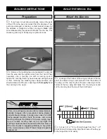
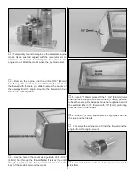
5. Thread a clevis 20 full turns onto each of the 6"
[150mm] pushrods.
❏
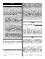
6. Attach the clevises to the torque rod horns. With the
servo centered, the servo arm parallel to the LE of the wings
and the ailerons centered, use a fine-point felt-tip pen to
mark the spot that the pushrods cross the outermost holes
in the servo arm.
❏
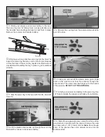
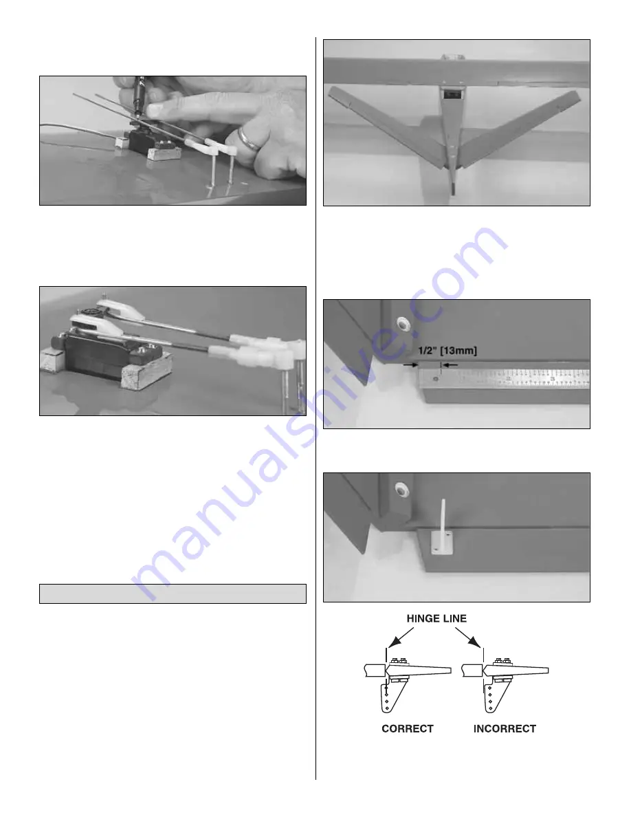
7. Slide the silicone retainers over the pushrods and onto
the clevises. Bend the pushrod upward 90 degrees on the
mark you made. Attach the pushrods to the servo arm with
two Faslinks. Cut off the excess pushrod. Be certain to leave
1/16" [2mm] of wire protruding from the Faslink as shown.
❏
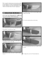
1. Cut the covering from the top and bottom of the V-tail
that covers both bolt holes. Cut the covering around the
hinge slots on the V-tail and the ruddervators the same as
you did with the wing. Permanently attach the ruddervators
to the V-tail the using the same hinging technique used with
the ailerons.
❏
2. Bolt the V-tail to the fuse with two 8-32 x 1-1/2" [38mm]
flat-head screws.
❏
3. Bolt the wing to the fuse with two 8-32 x 1-1/2" [38mm]
flat-head screws for the LE and two 8-32 x 3/4" [19mm] flat-
head screws for the TE.
❏
4. Stand two to three yards or meters behind the plane
and sight straight down the center of the fuse. Without
moving side to side, approach the plane until you can see if
the LE of the V-tail aligns with the TE of the wing. If they do
not align, sand the high side of the wing saddle a small amount
at a time until the wing and V-tail align with each other.
❏
5. Mark the top LE of both ruddervators 1/2" [13mm] from
the inboard edge.
❏
6. Position the control horn centered over the mark. Mark
the hole locations on the ruddervators. Drill 1/16" [1.6mm]
holes through the ruddervators for mounting the control
Assemble & Mount the V-tail
9

