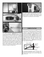
This airplane has been designed to utilize two servos for the
elevator with a minimum torque of 54 oz. in. each. The
rudder can utilize either one or two servos with a total torque
output of at least 100 oz. in.
❏
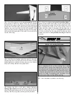
1. Cut the covering away from the openings in the rear of
the fuselage for the elevator and rudder servos. The elevator
servos are located in the upper servo openings. The rudder
servos are in the lower servo openings. When cutting the
covering away for the rudder, only cut out the covering for
the number of servos you will be using. It does not matter
into which side of the fuselage you choose to install the
rudder servo.
❏
2. Install a 24" [610mm] servo extension onto each of the
servo leads. Secure the extension to the lead with tape, a
piece of shrink tube or some other method to keep them
from coming unplugged.
❏
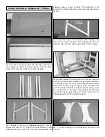
3. Install the elevator and rudder servos into the servo
openings. Drill through the servo mounting holes with a
1/16" [1.6mm] drill bit. Remove the servo from the servo
opening. Install and then remove a servo mounting screw
into each of the holes you have drilled. Apply a drop of thin
CA into the holes to harden the threads. Once the glue has
hardened, install the servo into the servo opening using the
hardware included with your servo. Center the servo and
then install a servo arm as shown. If you want to achieve 3D
throws we recommend the use of longer servo arms. The
Great Planes 1-1/2" [38mm] aluminum servo arm
(GPMM1105) works well for this.
❏
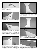
4. Place a nylon control horn in line with the outer hole in
the servo arm. When positioned properly, the control horn
will rest on a hardwood plate in the elevator. Mark the
location of the mounting holes onto the elevator. Drill a 3/32"
[2.5mm] hole on the marks, drilling through the plywood
plate
but not through the top of the elevator. Insert and
remove a #4 x 1/2" [13mm] screw into each of the holes.
Apply a couple drops of thin CA into the holes to harden the
threads. Once the glue has hardened, attach the control
horn to the elevator with two #4 x 1/2" [13mm] screws.
❏
5. Repeat this procedure for the rudder servo/servos. If
you are installing two rudder servos, the rudder control
horns will be opposite each other, making it difficult to mount
them with the #4 screws. Instead mount the control horns to
the rudder with four #4 x 1" [25mm] socket-head cap screws
and four 4-40 lock nuts as shown in the sketch.
❏
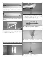
6. Thread a 4-40 nut onto a 4-40 x 12" [305mm] threaded
rod approximately twenty turns. Slide a silicone clevis
retainer onto a threaded 4-40 metal clevis. Then, thread the
clevis onto the rod, tightening it against the nut. Install the
clevis onto the nylon control horn. Install an unthreaded
solder clevis onto the servo arm. Center the elevator and the
servo. Next, mark the position the wire should be cut to fit
into the solder clevis. Remove all of the pushrod
components from the servo and control horn. Cut the wire
and on the mark and then solder the clevis to the wire.
❏
7. After the rod has cooled, install a clevis retainer onto
the clevis you have just soldered. Install the pushrod onto
Install the Elevator & Rudder Servos
18
Содержание ultimate!
Страница 33: ...33 Fuji IMVAC BT 43 EIS Engine Mounting Template O S 1 60 Engine Mounting Template...
Страница 34: ...34...


