❏
1. If you have not done so already, remove the major
parts of the kit from the box and inspect for damage. If any
parts are damaged or missing, contact Product Support at
the address or telephone number listed in the
“Kit
Inspection” section on page 6.
❏
2. Remove the tape and separate the ailerons and flaps
from the wing and the elevators from the stab. Use a
covering iron with a covering sock on high heat to tighten the
covering if necessary. Apply pressure over sheeted areas to
thoroughly bond the covering to the wood.
Do the bottom right wing first so your work matches the
photos the first time through.
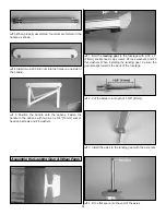
❏ ❏ ❏ ❏
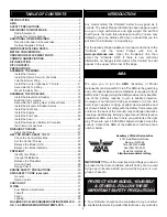
1. Drill a 3/32" [2.4mm] hole, 1/2" [13mm] deep
in the center of each hinge slot to allow the CA to “wick” in.
Follow-up with a #11 blade to clean out the slots. Hint: If you
have one, use a high-speed rotary tool to drill the holes.
❏ ❏ ❏ ❏
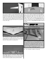
2. Use a sharp #11 blade to cut a strip of covering
from the hinge slots in the wing and aileron.
❏
3. Cut sixteen 1" x 1" [25 x 25mm] hinges from a CA
hinge strip. Snip off the corners so they go in easier.
❏ ❏ ❏ ❏
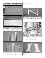
4. Test fit the ailerons to the wing with the
hinges. If the hinges don’t remain centered, stick a pin
through the middle of the hinge to hold it in position.
❏ ❏ ❏ ❏
5. Remove any pins you may have inserted into
the hinges. Adjust the aileron so there is a small gap
between the LE of the aileron and the wing. The gap should
be small, just enough to see light through or to slip a piece
of paper through.
❏ ❏ ❏ ❏
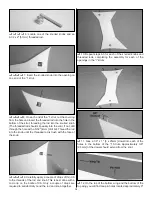
6. Apply six drops of thin CA to the top and bottom
of each hinge. Do not use CA accelerator. After the CA has
fully hardened, test the hinges by pulling on the aileron.
❏
7. Repeat steps 1 to 6 for the left wing panel and the two
wing panels for the top wing.
Install the Ailerons
ASSEMBLE THE WINGS
PREPARATIONS
7
Содержание ultimate!
Страница 33: ...33 Fuji IMVAC BT 43 EIS Engine Mounting Template O S 1 60 Engine Mounting Template...
Страница 34: ...34...


