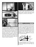
the elevator and servo. Follow the same procedure for the
rudder pushrod.
❏
8. Using the same method, install the pushrod linkage to
the opposite elevator and the rudder (if a second rudder is
to be used).
The tail wires are a functional component of this aircraft. DO
NOT fly the plane without the wires.
❏
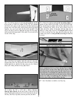
1. Examine this sketch closely. It shows the assembly of the
tail wire attachment posts. The parts are bagged together and
are pre-assembled. You can see that the wire threads through
the holes in the post and is retained by the set screw and the
small steel ball.
You will be able to assemble the wires without
taking the components of the post apart. If you find a need to
disassemble the post be very careful not to let any of the
parts fall out where you will not be able to find them. The ball
and set screw are very small! Four extra balls are included in
the bag. There is no need to disassemble the post to assemble
the flying wires! These are extras in case you should ever lose
one in the assembly.
Do not install the wires without the ball! If you simply tighten
the set screw against the wire it will eventually break the wire!
❏
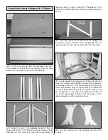
2. The location of the wire attachment points are located
with a pin hole in the stab and fin. Cut the covering to reveal
the mounting holes. Insert a 2-56 x 5/8" [16mm] machine
screw and #2 flat washer into one of the pre-assembled
wires. Insert the screw, washer and wire into the forward
hole in the fin. On the other side of the fin, insert another
wire over the screw followed by another #2 washer and a
2-56 nut. It is a good idea to apply a drop of Threadlocker to
the threads of the screw before installing the nut. Tighten the
nut to the screw but do not overtighten it, crushing the
wood. Repeat this step for the rear hole in the fin.
❏
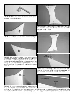
3. Holes for the wire attachment hardware are indicated
by pin hole on the stab. Locate the hole and then run a 5/32"
[4mm] drill bit through the holes. Do this for both of the holes
on each half of the stab. Install a post into one of the holes
located in the stab. Slide the retainer clip over the post on
the bottom of the stab, pushing it snugly against the bottom
of the stab.
❏
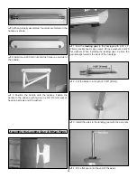
4. Loosen the set screw. Slide the wire through the hole
in the post and under the ball located in the post. Without
removing the set screw, apply a small amount of
Threadlocker onto the threads of the set screw. Do not
tighten the wire yet; just lightly tighten the set screw to hold
the wire in the post. Do this for all four of the posts.
❏
5. Insert the remaining four wires into the holes in the
bottom of the posts using the same procedure used on the
top of the stab.
Install the Tail Wires
19
Содержание ultimate!
Страница 33: ...33 Fuji IMVAC BT 43 EIS Engine Mounting Template O S 1 60 Engine Mounting Template...
Страница 34: ...34...


