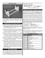
GREAT PLANES U-Can-Do SF Скачать руководство пользователя страница 5

5

Building Stand

A building stand or cradle comes in handy during the build. 

We use the Robart Super Stand II (ROBP1402) for all our 

projects in R&D, and it can be seen in pictures throughout 
this manual.

IMPORTANT BUILDING NOTES

   When you see the term 

test fi t

 in the instructions, it means 

that you should fi rst position the part on the assembly 

without using any glue

, then slightly modify or

 custom 

fi t

 the part as necessary for the best fi t.

   Whenever the term 

glue

 is written you should rely upon 

your experience to decide what type of glue to use. When 
a specifi c type of adhesive works best for that step, the 

instructions will make a recommendation.

   Whenever just 

epoxy

 is specifi ed you may use 

either


30-minute (or 45-minute) epoxy 

or

 6-minute epoxy. When 

30-minute epoxy is specifi ed it is 

highly 

recommended that 

you use only 30-minute (or 45-minute) epoxy, because you 
will need the working time and/or the additional strength.


Photos

 and 

sketches

 are placed 

before

 the step they 

refer to. Frequently you can study photos in following steps 
to get another view of the same parts.

   The stabilizer and wing incidences and engine thrust 

angles have been factory-built into this model. However, 
some  technically-minded  modelers  may  wish  to  check 
these measurements anyway. To view this information 
visit the web site at www.greatplanes.com and click on 

“Technical Data.” Due to manufacturing tolerances which 

will have little or no effect on the way your model will fl y, 
please expect slight deviations between your model and 
the published values.

KIT INSPECTION

Before starting to build, take an inventory of this kit to make 
sure it is complete, and inspect the parts to make sure they 
are of acceptable quality. If any parts are missing or are 
not  of  acceptable  quality,  or  if  you  need  assistance  with 
assembly, contact 

Product Support

. When reporting defective 

or missing parts, use the part names exactly as they are 
written in the Kit Contents list.

Great Planes Product Support

3002 N Apollo Drive, Suite 1


Ph: (217) 398-8970, ext. 5

Champaign, IL 61822 

Fax: (217) 398-7721

E-mail: [email protected]

ORDERING REPLACEMENT PARTS

Replacement parts for the Great Planes U-Can-Do SF are 
available using the order numbers in the 

Replacement Parts 

List

 that follows. The fastest, most economical service can 

be provided by your hobby dealer or mail-order company.

To locate a hobby dealer, visit the Hobbico web site at www.

hobbico.com. Choose “Where to Buy” at the bottom of the menu 
on the left side of the page. Follow the instructions provided 
on the page to locate a U.S., Canadian or International dealer.

Parts may also be ordered directly from Hobby Services by 
calling (217) 398-0007, or via facsimile at (217) 398-7721, but 
full retail prices and shipping and handling charges will apply. 
Illinois and Nevada residents will also be charged sales tax. 
If ordering via fax, include a Visa or MasterCard number and 
expiration date for payment.

  Mail parts orders 

Hobby Services

  and payments by  3002 N Apollo Drive, Suite 1
  personal check to:  Champaign IL  61822

Be certain to specify the order number exactly as listed in the 

Replacement Parts List

. Payment by credit card or personal 

check only; no C.O.D.

If additional assistance is required for any reason contact 
Product Support by e-mail at productsupport@greatplanes.
com, or by telephone at (217) 398-8970.

Order No.

Description

Fuselage

Wing / Ailerons

Horizontal Stabilizer / Elevators

Fin / Rudder

Cowl

Hatch

Landing Gear

Wheel Pants

Spinner

EP Motor Mount

Side Force Plates

Pushrods

Tail Wheel Assembly

GPMA4335

GPMA4336

GPMA4337

GPMA4338

GPMA4339

GPMA4340

GPMA4341

GPMA4342

GPMA4343

GPMA4344

GPMA4345

GPMA4346

GPMA4347

REPLACEMENT PARTS LIST

Содержание U-Can-Do SF

Страница 1: ...l resulting liability If the buyer is not prepared to accept the liability associated with the use of this product the buyer is advised to return this kit immediately in new and unused condition to th...

Страница 2: ...57 Or via the Internet at http www modelaircraft org IMPORTANT Two of the most important things you can do to preserve the radio controlled aircraft hobby are to avoid flying near full scale aircraft...

Страница 3: ...l that is straight and true DECISIONS YOU MUST MAKE This is a partial list of items required to finish the U Can Do SF that may require planning or decision making before starting to build Order numbe...

Страница 4: ...only Adhesives and Building Supplies This is the list of Adhesives and Building Supplies that are required to finish the U Can Do SF ARF 1 2 oz 15g Thin Pro CA GPMR6001 Pro 6 minute or 30 minute epox...

Страница 5: ...re not of acceptable quality or if you need assistance with assembly contact Product Support When reporting defective or missing parts use the part names exactly as they are written in the Kit Content...

Страница 6: ...if necessary Apply pressure over sheeted areas to thoroughly bond the covering to the wood INSTALL THE AILERON SERVOS PUSHRODS AND BELLY PAN CUT OFF UNUSED ARMS 1 Center your aileron servos with your...

Страница 7: ...tring Pull the string through the hole Use the string to pull the servo leads through the wing and out the hole 4 Fit the servos into the servo openings and drill 1 16 1 6mm holes through the mounting...

Страница 8: ...ey cross the outer holes in the servo arms 9 Clean the area of the pushrods between the marks you made and the threads with a paper towel dampened with denatured alcohol Apply a thin coating of epoxy...

Страница 9: ...the covering between the lines you drew HOW TO CUT COVERING FROM BALSA Use a soldering iron to cut the covering from the stab The tip of the soldering iron doesn t have to be sharp but a fine tip doe...

Страница 10: ...exposed wood with 30 minute epoxy although messy a more reliable glue joint can be attained if you also coat the inside edges of the stab pocket Reinstall the stab and properly position it in the poc...

Страница 11: ...rudder and clean the rudder end of the wire with denatured alcohol Apply a few drops of oil along the hinge of the nylon tab Coat the inside of the fin slot with epoxy as well as the rudder end of the...

Страница 12: ...l the rudder pushrod in the same manner using the remaining 5 7 8 150mm carbon tube 11 Apply a drop or two of oil onto the tail wheel axle and slide on the tail wheel Secure it in place with a 1 8 3 2...

Страница 13: ...ks Be sure to drill the holes as shown in the picture It is recommended to start with a small drill bit and work your way up in size to 11 64 4 4mm Doing this will improve accuracy in the positioning...

Страница 14: ...piece of dowel into each hole and sand them flush with the sides of the motor mount 6 Attach the brushless motor mount to the firewall using four 6 32 x 3 4 19mm machine screws four 6 flat washers fo...

Страница 15: ...ws and three 4 flat washers If you are using an ESC other than the one recommended you may need to modify the tray or mount the ESC in a different manner 11 Connect the motor wires to the ESC route th...

Страница 16: ...nes running horizontally and vertically depending on the engine model A 55AX O S engine stock muffler will fit in the cavity without the need to cut away the bottom of the cowl The 65AX stock muffler...

Страница 17: ...hand fill the perforated cutout lines for the cooling hole and ESC tray slots in the firewall These cutouts are for the brushless installation only and should be glued in place for a glow engine setu...

Страница 18: ...ft uncut With the tubes installed in the stopper fit the stopper plates loosely in place with the 3 x 25mm phillips screw to hold the assembly together 8 Make a strap 12 305mm long by overlapping the...

Страница 19: ...r GPMR8130 to mark the location of the engine tab mounting holes onto the engine mount rails 14 Use four 6 32 x 3 4 19mm machine screws four 6 lock washers and four 6 flat washers to attach the engine...

Страница 20: ...h the servo arm to the throttle servo perpendicular to the servo case be sure to install the servo arm screw Adjust the carb barrel so that it is close to 50 open and tighten the set screw in the scre...

Страница 21: ...ad The balancing connector will remain accessible through the canopy hatch To help prevent inadvertent charging of a LiFe battery through this jack without also connecting the balancing connector we i...

Страница 22: ...n the locations shown two on each side Mark onto the tape pieces exactly where the cowl mounting screw holes will be drilled The holes should be located in the center of the thickness of the firewall...

Страница 23: ...rs 7 Install the propeller and spinner onto the motor You may need to enlarge the hole in the prop and spinner backplate with a reamer or drill to match the prop shaft of your power system It may also...

Страница 24: ...cket with a mixture of liquid dish soap and warm water about one teaspoon of soap per gallon of water Submerse the decal in the soap and water and peel off the paper backing Note Even though the decal...

Страница 25: ...e throws ELEVATOR HIGH LOW 1 25mm 15 3 4 19mm 11 15 16 24mm 12 5 8 16mm 8 2 1 2 64mm 23 1 1 8 29mm 10 RUDDER AILERONS 3D 2 5 16 59mm 36 1 1 2 38mm 20 4 102mm 39 Up Down Up Down Right Left IMPORTANT Th...

Страница 26: ...reatest mechanical advantage of the servo over the control surface which will increase the servo s centering capabilities and output torque minimize any free play in the system and allow high ATV sett...

Страница 27: ...to minimize or eliminate any additional ballast required If additional weight is required nose weight may be easily added by using a spinner weight GPMQ4645 for the 1 oz 28g weight or GPMQ4646 for th...

Страница 28: ...rrectly do not fly Find and correct the problem first Look for loose servo connections or broken wires corroded wires on old servo connectors poor solder joints in your battery pack or a defective cel...

Страница 29: ...nstructions Be sure to check the items off as they are completed that s why it s called a check list 1 Check the C G according to the measurements provided in the manual 2 Be certain the battery and r...

Страница 30: ...w the model handles at slower speeds Add power to see how the model climbs as well Continue to fly around executing various maneuvers and making mental notes or having your assistant write them down o...

Страница 31: ...will go It is possible to get the flat spin without falling and it is also possible to climb during the spin Inverted Flat Spins This is the same as the up right flat spin except most planes like to...

Страница 32: ...ng this maneuver Some planes perform better with more elevator deflection and a farther forward C G while other planes prefer a further aft C G and less elevator deflection Elevator to flap mixing can...

Отзывы: