GREAT PLANES U-Can-Do SF Скачать руководство пользователя страница 16

16

❏ 

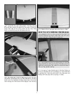
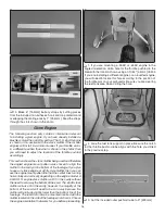
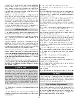
14. Make 6" [152mm] battery straps by cutting pieces 

from the included non-adhesive hook and loop material and 
overlapping the mating ends by 1" [25.4mm]. Feed the straps 
through the slots shown in the photo.

Glow Engine

The following section only contains information relevant 

to installing a glow engine. If you have already installed a 
brushless motor then skip this section. The O.S. .65 AX engine 
is shown in this section with the stock muffl er. Other model 
engines will install in a similar manner. If your throttle arm is 
in a different position than what is shown in the photos then 

you will need to adjust the location of the throttle pushrod 

accordingly.

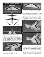
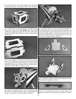
This section shows the stock muffl er being used and therefore 

the angled engine mount pattern was chosen to align the 
muffl er in the cavity on the bottom of the fuselage. If you plan 
to use a 4-stroke engine or a Pitts style muffl er, then you can 
use the engine mount pattern that has the center lines running 
horizontally and vertically depending on the engine model. A 

.55AX O.S. engine stock muffl er will fi t in the cavity without 

the need to cut away the bottom of the cowl. The .65AX stock 
muffl er will also fi t in the cavity; however, the majority of the 
bottom  of  the  cowl  will  need  to  be  cut  away  because  the 
muffl er will protrude slightly lower than the bottom line of the 
fuselage. The .65AX can also be mounted inverted with the 
muffl er located on the side of the fuselage (not shown). Choose 
the engine orientation that works for you before proceeding.

❏ 

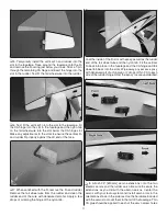
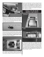
1. If you are mounting a .55AX or .65AX engine in the 

angled orientation, drill a hole for the throttle pushrod in the 
fi rewall in the location shown using an 11/64" [4.4 mm] drill bit. 
If you are installing a different engine or an inverted engine, 
you will need to locate this hole according to the position of 
the throttle arm on your carburetor. Be sure you are clearing 
the fuel tank area when drilling the hole.

❏ 

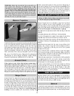
2. Glue the fuel tank support in place. Be sure the notch 

for the throttle pushrod tube aligns with the hole you drilled 
in the previous step.

❏ 

3. Cut the included outer pushrod tube to 9" [ 229 mm].

Содержание U-Can-Do SF

Страница 1: ...l resulting liability If the buyer is not prepared to accept the liability associated with the use of this product the buyer is advised to return this kit immediately in new and unused condition to th...

Страница 2: ...57 Or via the Internet at http www modelaircraft org IMPORTANT Two of the most important things you can do to preserve the radio controlled aircraft hobby are to avoid flying near full scale aircraft...

Страница 3: ...l that is straight and true DECISIONS YOU MUST MAKE This is a partial list of items required to finish the U Can Do SF that may require planning or decision making before starting to build Order numbe...

Страница 4: ...only Adhesives and Building Supplies This is the list of Adhesives and Building Supplies that are required to finish the U Can Do SF ARF 1 2 oz 15g Thin Pro CA GPMR6001 Pro 6 minute or 30 minute epox...

Страница 5: ...re not of acceptable quality or if you need assistance with assembly contact Product Support When reporting defective or missing parts use the part names exactly as they are written in the Kit Content...

Страница 6: ...if necessary Apply pressure over sheeted areas to thoroughly bond the covering to the wood INSTALL THE AILERON SERVOS PUSHRODS AND BELLY PAN CUT OFF UNUSED ARMS 1 Center your aileron servos with your...

Страница 7: ...tring Pull the string through the hole Use the string to pull the servo leads through the wing and out the hole 4 Fit the servos into the servo openings and drill 1 16 1 6mm holes through the mounting...

Страница 8: ...ey cross the outer holes in the servo arms 9 Clean the area of the pushrods between the marks you made and the threads with a paper towel dampened with denatured alcohol Apply a thin coating of epoxy...

Страница 9: ...the covering between the lines you drew HOW TO CUT COVERING FROM BALSA Use a soldering iron to cut the covering from the stab The tip of the soldering iron doesn t have to be sharp but a fine tip doe...

Страница 10: ...exposed wood with 30 minute epoxy although messy a more reliable glue joint can be attained if you also coat the inside edges of the stab pocket Reinstall the stab and properly position it in the poc...

Страница 11: ...rudder and clean the rudder end of the wire with denatured alcohol Apply a few drops of oil along the hinge of the nylon tab Coat the inside of the fin slot with epoxy as well as the rudder end of the...

Страница 12: ...l the rudder pushrod in the same manner using the remaining 5 7 8 150mm carbon tube 11 Apply a drop or two of oil onto the tail wheel axle and slide on the tail wheel Secure it in place with a 1 8 3 2...

Страница 13: ...ks Be sure to drill the holes as shown in the picture It is recommended to start with a small drill bit and work your way up in size to 11 64 4 4mm Doing this will improve accuracy in the positioning...

Страница 14: ...piece of dowel into each hole and sand them flush with the sides of the motor mount 6 Attach the brushless motor mount to the firewall using four 6 32 x 3 4 19mm machine screws four 6 flat washers fo...

Страница 15: ...ws and three 4 flat washers If you are using an ESC other than the one recommended you may need to modify the tray or mount the ESC in a different manner 11 Connect the motor wires to the ESC route th...

Страница 16: ...nes running horizontally and vertically depending on the engine model A 55AX O S engine stock muffler will fit in the cavity without the need to cut away the bottom of the cowl The 65AX stock muffler...

Страница 17: ...hand fill the perforated cutout lines for the cooling hole and ESC tray slots in the firewall These cutouts are for the brushless installation only and should be glued in place for a glow engine setu...

Страница 18: ...ft uncut With the tubes installed in the stopper fit the stopper plates loosely in place with the 3 x 25mm phillips screw to hold the assembly together 8 Make a strap 12 305mm long by overlapping the...

Страница 19: ...r GPMR8130 to mark the location of the engine tab mounting holes onto the engine mount rails 14 Use four 6 32 x 3 4 19mm machine screws four 6 lock washers and four 6 flat washers to attach the engine...

Страница 20: ...h the servo arm to the throttle servo perpendicular to the servo case be sure to install the servo arm screw Adjust the carb barrel so that it is close to 50 open and tighten the set screw in the scre...

Страница 21: ...ad The balancing connector will remain accessible through the canopy hatch To help prevent inadvertent charging of a LiFe battery through this jack without also connecting the balancing connector we i...

Страница 22: ...n the locations shown two on each side Mark onto the tape pieces exactly where the cowl mounting screw holes will be drilled The holes should be located in the center of the thickness of the firewall...

Страница 23: ...rs 7 Install the propeller and spinner onto the motor You may need to enlarge the hole in the prop and spinner backplate with a reamer or drill to match the prop shaft of your power system It may also...

Страница 24: ...cket with a mixture of liquid dish soap and warm water about one teaspoon of soap per gallon of water Submerse the decal in the soap and water and peel off the paper backing Note Even though the decal...

Страница 25: ...e throws ELEVATOR HIGH LOW 1 25mm 15 3 4 19mm 11 15 16 24mm 12 5 8 16mm 8 2 1 2 64mm 23 1 1 8 29mm 10 RUDDER AILERONS 3D 2 5 16 59mm 36 1 1 2 38mm 20 4 102mm 39 Up Down Up Down Right Left IMPORTANT Th...

Страница 26: ...reatest mechanical advantage of the servo over the control surface which will increase the servo s centering capabilities and output torque minimize any free play in the system and allow high ATV sett...

Страница 27: ...to minimize or eliminate any additional ballast required If additional weight is required nose weight may be easily added by using a spinner weight GPMQ4645 for the 1 oz 28g weight or GPMQ4646 for th...

Страница 28: ...rrectly do not fly Find and correct the problem first Look for loose servo connections or broken wires corroded wires on old servo connectors poor solder joints in your battery pack or a defective cel...

Страница 29: ...nstructions Be sure to check the items off as they are completed that s why it s called a check list 1 Check the C G according to the measurements provided in the manual 2 Be certain the battery and r...

Страница 30: ...w the model handles at slower speeds Add power to see how the model climbs as well Continue to fly around executing various maneuvers and making mental notes or having your assistant write them down o...

Страница 31: ...will go It is possible to get the flat spin without falling and it is also possible to climb during the spin Inverted Flat Spins This is the same as the up right flat spin except most planes like to...

Страница 32: ...ng this maneuver Some planes perform better with more elevator deflection and a farther forward C G while other planes prefer a further aft C G and less elevator deflection Elevator to flap mixing can...

Отзывы: