11
❏
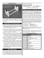
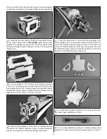
5. Temporarily install the vertical fi n and rudder into the
slot in the fuselage. Trace around the fuselage onto the fi n
and remove the covering just below your lines. Stick a T-pin
through the remaining CA hinge and insert the hinge into the
slot in the rudder. Test fi t the tail wheel wire into the rudder.
❏
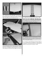
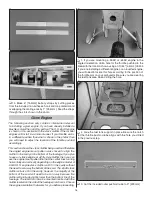
6. Test fi t the vertical fi n into the slot in the fuselage. Fit
the CA hinge into the slot in the fuselage and the nylon tab
on the tail wheel wire into the slot below the CA hinge slot.
Make any adjustments to the slots to ensure the vertical fi n
and rudder fi t properly against the aft end of the fuse.
❏
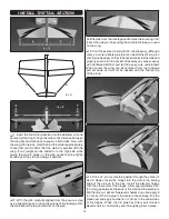
7. When satisfi ed with the fi t, remove the fi n and rudder.
Remove the tail wheel wire from the rudder and clean the
rudder end of the wire with denatured alcohol. Apply a few
drops of oil along the hinge of the nylon tab.
Coat the inside of the fi n slot with epoxy as well as the rudder
end of the tail wheel wire and the nylon tab. Fit the vertical
fi n back into place in the fuselage and the CA hinge and tail
wheel tab back into the slots. Wipe away any excess epoxy
with denatured alcohol. Apply 6 or 7 drops of thin CA to each
side of the rudder hinge. Allow the epoxy to cure undisturbed.
❏
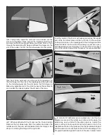
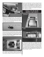
8. Attach 24" [610mm] servo extensions onto the two
elevator servos and the rudder servo. Be sure to secure the
extensions as you did with the aileron servos. Center the
servos with your radio system and install servo arms in the
orientations shown in the pictures. Use the hardware included
with the servos to mount them in the tail of the fuselage. Thin
CA glue should be applied to each of the servo screw holes.


