7
❏
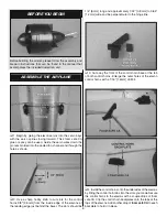
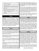
5. Cut three arms from two four-armed servo arms. Enlarge
the outer holes in the servo arms with a 1/16" [1.6mm] drill bit.
❏
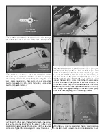
6. Attach a pushrod wire with a Z-bend at one end to
the outer hole of each servo arm. Secure the servo arms to
the servos parallel to the elevon hinge line using the servo
arm screws included with the servos. Attach a screw-lock
pushrod connector to each control horn using a screw-lock
pushrod connector retainer.
❏
7. Insert the other end of the pushrod wires into the screw-
lock pushrod connectors. Position the elevons in the neutral
position and thread a knurled thumb screw into the screw-lock
connectors. Tighten the screws against the pushrod wires.
❏
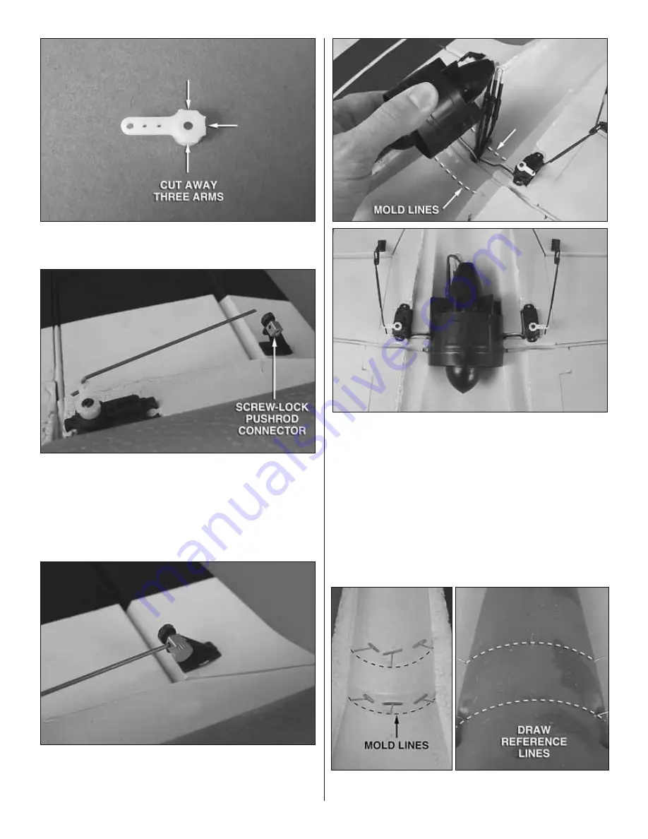
8. Attach 2mm female to 3.5mm male bullet adapters (not
included) to the leads on the brushless motor. Mix up a small
batch of 6-minute epoxy. Brush on a thin coat of epoxy inside
the duct channel between the mold lines for the ducted fan
unit. From the top of the plane, feed the motor leads on the
ESC through the same hole that the servo wires use and
connect the leads to the motor. Confi rm that the servo leads
are still positioned in the grooves in the duct channel. Fit
the ducted fan unit into position at the mold lines. The motor
leads should fi t into the notch just behind the hole that they
pass through. We suggest holding the ducted fan unit tightly
in place as the epoxy begins the hardening process.
❏
9. After your model is assembled, the only way to remove
the ducted fan unit in case of repair or replacement is to cut


