8
it out from the bottom. Because of this, we suggest marking
the location of the ducted fan unit on the underside of the
lower duct channel half. You can do this by pushing T-pins
through the inside of the duct channel half along the edges of
the mold lines. The holes left on the underside of the channel
half from the T-pins can be connected with a drawn line for
future reference. If at any time you need to remove the fan
unit, use a hobby knife to cut along the holes left by the T-pins
to extract the unit out of the bottom of the plane.
❏
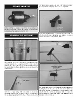
10. Use thick CA glue or mix up approximately 3/8oz [5cc]
of epoxy to glue the lower duct channel half onto the fuselage.
Coat the area in duct channel half between the fan unit mold
lines with a thin coat of glue or epoxy. Coat the edges of the
duct channel half (being sure to use enough adhesive along
all
contact surfaces) and press the piece into place aligning
the front air intake edges with the underside of the fuselage.
Wipe away any excess glue with a dry paper towel.
❏
11. Glue the aft duct channel ring into place with thick CA
glue or epoxy.
❏
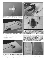
12. Connect the servos and ESC to the receiver. Install
the receiver and ESC in the locations shown. They can be
secured using small pieces of the included hook and loop
material or double-sided foam servo tape (not included).
❏
13. The receiver antenna can be taped to the side of
the fuselage anywhere that it will not interfere with the duct
channel or canopy. For a clean look, we drilled a 3/32" [2.4mm]
diameter hole from the front of the lower duct channel where
it meets the fuselage up to the radio compartment. Be very
careful not to drill into the duct channel. Feed the receiver
antenna through the hole and out the bottom of the fuselage.
The antenna can then be tucked into the seam between the
lower duct channel and the fuselage. A few drops of thick CA
glue will prevent the antenna from falling out of the seam.


