background image

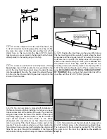
8. Inside the fuselage locate the two elevator pushrods.

The pushrod closest to the center of the fuselage needs to
be cut. Cut the pushrod wire 2-1/4" [57mm] from the end of
the plastic outer pushrod tube.

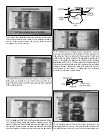
9. Bend the inside elevator pushrod wire as shown so that

both wires are parallel to one another. Be sure there is at
least 1" [25mm] at the end of the pushrod wire that is parallel
to the other pushrod.

10. Locate two 5/32" [4mm] wheel collars and two 6-32 x

1/4" [12mm] socket head cap screws. Install a screw into
each of the wheel collars. Slide both wheel collars over the
two elevator pushrod wires. Position the elevators the same
and then tighten the wheel collar screws onto the two wires.

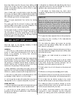
11. Following the manufacturer’s instructions for your

radio system, install the rubber grommets and eyelets onto
three servos. Place the servos for the elevators, throttle and
rudder onto the servo mount in the fuselage. Position each
servo in line with the pushrod as shown. Once properly
positioned drill a 1/16" [1.5mm] pilot hole through each of
the servo mounting holes and into the servo mount. After
drilling the holes, harden the holes with a drop of thin CA.
Screw each of the servos in place with the hardware
provided by the radio manufacturer.

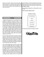
12. Position each of the servo arms as shown in the

photograph. Make a mark on the elevator pushrod wire over
the outboard hole of the servo arm. On this mark make a 90°

20

Содержание Ju-87 Stuka

Страница 1: ...By the act of using the user assembled product the user accepts all resulting liability If the buyer is not prepared to accept the liability associated with the use of this product the buyer is advise...

Страница 2: ...le the model according to the instructions Do not alter or modify the model as doing so may result in an unsafe or unflyable model In a few cases the instructions may differ slightly from the photos I...

Страница 3: ...nute Epoxy GPMR6045 30 Minute Epoxy GPMR6047 Hobby knife HCAR0105 11 blades HCAR0211 Small T pins HCAR5100 Builder s triangle HCAR0480 Electric drill Small phillips and flat blade screwdrivers HCAR104...

Страница 4: ...nated by a number and a length For example 6 x 3 4 This is a number six screw that is 3 4 long Machine screws are designated by a number threads per inch and a length For example 4 40 x 3 4 This is a...

Страница 5: ...et screw for tail wheel collar 6 4 x 3 8 Sheet metal screw mounting the cowl 6 4 Washers mounting the cowl 1 Wire tail wheel 4 1 x 1 Servo mounting tape for mounting the aileron servos 3 2 56 x 36 Pus...

Страница 6: ...be used for pulling the servo wires through the wing when the radio installation takes place 3 Test fit the outer wing joiner to the wing panel and the inner wing panel Be sure the wing panel is asse...

Страница 7: ...he hinge plate will face the top of the control surface 8 Apply a small drop of oil or a dab of petroleum jelly onto each of the hinge joints This will prevent the glue from getting into the hinge joi...

Страница 8: ...ve photograph For easy reference we have drawn the circles onto the covering This should help you locate each of the mounts These mounts are what you will be screwing the hinge plates to as we proceed...

Страница 9: ...unting screws with a felt tip marker onto the wing Drill a 1 16 1 5mm hole through each of these marks into the wing BE CAREFUL NOT TO DRILL THROUGH THE TOP OF THE WING Once you have the holes drilled...

Страница 10: ...for the left wing panel 26 Locate the plywood center wing joiner Test fit it into the right and left wing halves When fitting it into the wing make sure that the joiner angles downward 27 When you are...

Страница 11: ...en remove the fairing and the wing 31 Cut away a 1 2 13mm strip of covering inside each of the lines you have drawn Be careful not to cut into the surface of the wing sheeting This could weaken the st...

Страница 12: ...horizontal stabilizer into the slot in the fuselage 4 Measure from the end of the stab to each wing tip and from the center of the fuselage out to the end of the stab as shown in the sketch 5 Once you...

Страница 13: ...age onto the fin Then cut the covering away using the same technique used for the stab 9 Test fit the fin into the slot Use a builders triangle to be sure that the fin is 90 degrees to the stab When y...

Страница 14: ...easier when installing the hinges 4 Install a pin into the center of three hinges then install one hinge in each of the slots in one of the elevator halves Install the hinge until the pin is touching...

Страница 15: ...t in the end of the fuselage from the mark you made to the bottom of the fuselage Insert the nylon bearing into the slot When you are satisfied with the fit glue the nylon bearing to the fuselage with...

Страница 16: ...ce you have the engine properly positioned on the engine mount mark the location of the engine mounting holes on the rails of the engine mount A great tool for doing this is the Great Planes Dead Cent...

Страница 17: ...e the wheel and axle onto the landing gear wire Position the axle and wheel as shown Position the wheel pant so that the wheel is centered in the pant Mark the location of the wheel pant on the wing w...

Страница 18: ...the cowling may make it difficult to access the carburetor You can also install a third line to the tank and use it for filling the tank The method you use is your choice but make your decision befor...

Страница 19: ...he pushrod Make both bends on the solid wire 5 Repeat step 4 for the other half of the elevator 6 Drill a 3 16 5mm hole in firewall This hole should be in close alignment to the carburetor Locate the...

Страница 20: ...n the elevators the same and then tighten the wheel collar screws onto the two wires 11 Following the manufacturer s instructions for your radio system install the rubber grommets and eyelets onto thr...

Страница 21: ...aph With the servo horn installed as shown this servo will be used in the left wing panel 3 The servos for the ailerons are installed with servo tape To insure the strongest installation do not skip t...

Страница 22: ...string attached to the servo lead until you have completed the servo installation instructions 8 Locate one of the 2 56 x 6 152mm wire pushrods Install a nylon clevis and clevis retainer onto the thr...

Страница 23: ...3 4 x 3 4 9 5 x 19 x 19mm hardwood blocks Place them against the servo mounting tabs so that they act as a wedge forcing the servo against the side of the servo bay Using 6 minute epoxy glue them in...

Страница 24: ...om the servo arm to the flap 20 Install a small nylon control horn to the flap the same way you installed the aileron control horns 21 Locate one of the 2 56 x 6 152mm wire pushrods Install a nylon cl...

Страница 25: ...o connect the flaps and ailerons 5 Following the radio manufacturer s instructions connect the servos battery and switch to the radio receiver 6 Place another piece of foam rubber on top of the receiv...

Страница 26: ...onto the engine and re fit the cowl Make additional cutouts in the cowl to accommodate your muffler 6 Finish the final installation of the cowl by adding one additional 4 x 3 8 9 5mm machine screw in...

Страница 27: ...r and receiver and center the trims If necessary remove the servo arms from the servos and reposition them so they are centered Reinstall the screws that hold on the servo arms 2 With the transmitter...

Страница 28: ...the wing level have an assistant help you lift the model by the engine propeller shaft and the bottom of the fuse under the TE of the fin Do this several times 2 If one wing always drops when you lif...

Страница 29: ...break in the engine After break in confirm that the engine idles reliably transitions smoothly and rapidly to full power and maintains full power indefinitely After you run the engine on the model in...

Страница 30: ...craft in the presence of spectators until I become a qualified flier unless assisted by an experienced helper 3 I will perform my initial turn after takeoff away from the pit or spectator areas and I...

Страница 31: ...to come off the ground One of the most important things to remember with a taildragger is to always be ready to apply right rudder to counteract engine torque Gain as much speed as your runway and fl...

Страница 32: ...y shines when you lower the flaps Your approach is the same as just described except once you deploy the flaps you may need to add a bit more throttle to maintain flying speed Watch the plane as the f...

Отзывы: