8
HINGE LINE
CORRECT
INCORRECT
❏ ❏
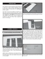
6. Cut the control horn and mounting plate apart. Attach
the clevis in the outer hole of a nylon control horn. Place the
control horn in line with the hole 3/4" [19mm] from the center
of the servo arm. When positioned properly the control horn
will rest on a hardwood plate in the aileron. Mark the location
of the mounting holes onto the aileron. Drill a 3/32" [2.4mm]
hole on the marks, drilling through the plywood plate and the
top of the aileron.
❏ ❏
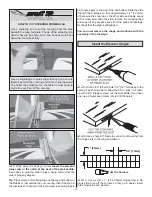
7. Insert two 2-56 x 5/8" [16mm] machine screws
through the control horn and aileron. Secure the control horn
to the aileron with the nylon control horn backplate.
❏ ❏
8. Slide a silicone clevis retainer over the clevis. With
the aileron servo and the aileron centered, mark the aileron
pushrod where it crosses the aileron servo arm. Make a 90°
bend at the mark. Cut the pushrod 3/8" [9.5mm] past the
bend. Attach the pushrod to the aileron servo arm with a
nylon FasLink.
❏ ❏
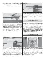
9. Glue the carbon fi ber anti rotation pin in the hole as
shown. The pin should protrude approximately 1/4" [6.4mm].
❏
10. Repeat steps 1 to 9 for the left wing panel.
ASSEMBLE THE FUSELAGE
Install the Main Landing Gear
❏ ❏
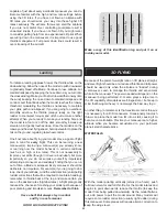
1. Insert a 4mm axle through the right main landing
gear. Secure the axle to the landing gear with a 5mm fl at
washer and 5mm lock nut. Note: The front of the main
landing gear sweeps forward.
❏ ❏
2. Install two 5mm fl at washers on the axle, then the
foam main wheel, followed by a 4.2mm wheel collar. Secure
the wheel collar on the axle with 6-32 set screw. Mark the
8


