background image

❏ 

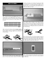
1. Locate the two 

plywood servo plates

. Position them as

shown in the photograph so that the forward plate is slightly
behind the former. The rear plate should be positioned behind
the forward plate the distance required for your servos. Leave
a 1/32" (.8mm) gap between the servos and the mounting
plates. When you are satisfied with the fit, use 6-minute epoxy
to glue the plates in position on the fuselage.

❏ 

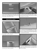
2. Use the following sequence for mounting the servos

into the servo tray.

❏ 

A. Install rubber grommets and brass eyelets in the

servos using the provided sketch.

❏ 

B. Test fit the servos in the tray. 

❏ 

C. Mark servo hole locations on the tray, then drill

1/16" (1.5mm) pilot holes through each mark.

❏ 

D. Mount the servos with the screws provided with

your radio system. Notice the orientation when installing.

❏ 

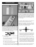
3. Following the manufacturer's recommendations, install

and hook up the three servos, the receiver, switch and battery
as shown in the photograph. Wrap the receiver and the
battery in foam and hold them in place by gluing small balsa
sticks (not included) above them. We added a Great Planes
Switch Mount and Charge Jack (GPMM1000, not included)
for convenience and ease of use at the field, installed on the
side of the fuselage.

❏ 

4. Prepare 

two

arm

style servo horn as follows but

don't install it on the servo until instructed to do so.

Note:

The size and shape of servo horns varies from

manufacturer to manufacturer. The sketches and photos
show a typical radio installation with standard horns. All
standard servo horns should fit the Big Stik.

❏ 

A. Cut off 

two

servo arms from 

four

servo horns

included with your radio control set to make them into
"one arm" servo horns. Use your bar sander to remove
the remaining jagged edges left from the cut off arms.

❏ 

B. Enlarge the holes in the horns with a 5/64" (2mm) drill.

❏ 

C. Turn on your transmitter and receiver, then

position the aileron, rudder, elevator and throttle trim
tabs on your transmitter to the center. This is called
"centering" the servos and will allow you to place the
servo horns on the servos in a neutral position. Attach
the arms to the servos as shown in the following photos.

❏ 

5. Prepare three 

one

arm

style servo horns following the

same step just done except cut off three unused arms.

RADIO INSTALLATION

13

Содержание Big Stir 40

Страница 1: ...user assembled product By the act of using the user assembled product the user accepts all resulting liability If the buyer is not prepared to accept the liability associated with the use of this prod...

Страница 2: ...which has more than 2 500 chartered clubs across the country Through any one of them instructor training programs and insured newcomer training are available Contact the AMA at the address or toll fre...

Страница 3: ...100 Heat Gun TOPR2000 Switch and Charge Jack GPMM1000 Fuel Filler Valve GPMQ4160 Remove the fuselage wing panels rudder assembly and stabilizer assembly from their bags Inspect all items closely to ch...

Страница 4: ...609 6mm 30 762mm 36 914 4mm Metric Conversions Parts List Big Stik 40 GPMA1225 Replacement Parts If needed replacement parts for your Big Stik 40 ARF are available through your hobby supplier Wing Kit...

Страница 5: ...be a great tool to add to you shop 4 Align the aileron in position at the trailing edge of the wing Be sure to leave at least a 1 6 1 6mm spacing between the aileron and the outboard trailing edge of...

Страница 6: ...in the root rib until the clevis shows in the servo bay Put the string onto the clevis and pull the string back through the hole 10 Pull the string out through the opening in the bottom of the wing s...

Страница 7: ...nter of the wing aligned with the mark on the bulk head drill two 1 4 6mm holes into the wing Drill the holes through the pre drilled holes that are in the bulk head 4 Insert the 1 4 6mm wooden dowel...

Страница 8: ...e and the center the drill on the wing plate 9 Remove the wing Use a 8 5 2mm or 13 64 drill bit and drill through the pilot holes in the wing bolt blocks Use a 1 4 20 tap to thread the wing bolt block...

Страница 9: ...t and rear The stabilizer tips should be equally spaced in relation to the wing If not lightly sand the high side of the stabilizer saddle to correct the problem Work slowly and check the alignment of...

Страница 10: ...and right corners of the firewall have pre drilled holes These holes are for the fuel and pressure line to pass through Check to be sure that the holes are large enough for your fuel line If not dril...

Страница 11: ...ything in place 2 Screw the spinner onto the backplate 1 Locate the aluminum landing gear Make a line 1 2 13mm from the leading and trailing edge of the center portion of the landing gear Make four ma...

Страница 12: ...in the firewall for the steering pushrod Place the other wheel collar on the top of the wire Tighten the set screws This will hold the wire in place 6 Locate two 5 32 4mm wheel collars and two 6 32 x...

Страница 13: ...sa sticks not included above them We added a Great Planes Switch Mount and Charge Jack GPMM1000 not included for convenience and ease of use at the field installed on the side of the fuselage 4 Prepar...

Страница 14: ...it through the enlarged hole in the servo arm Cut off the excess wire 3 8 9 5mm above the bend Secure the wire in place with a nylon FasLink 11 Follow the same steps for the rudder except you will ne...

Страница 15: ...e 3 8 9 5mm above the bend Secure the wire in place with a nylon FasLink 1 Install a Brass Screw lock Pushrod Connector with the 4 40 x 1 8 Cap Screw on the servo arm Snap the Nylon Retainer onto the...

Страница 16: ...throw outward will increase it Note Throws are measured at the widest part of the elevators rudder and ailerons We recommend the following control surface throws as a starting point Important Do not c...

Страница 17: ...sure that you have followed all of the instructions of the radio manufacturer including running the antenna out the fuselage to the tail Follow the battery charging procedure in your radio instructio...

Страница 18: ...by closing off the fuel line or following the engine manufacturer s recommendations Do not use hands fingers or any other body part to try to stop the engine To stop a gasoline powered engine an on of...

Страница 19: ...leron servos with the aerobatic potential of a symmetrical airfoil Note Pilot figure not included Piper J 3 Cub ARF GPMA1310 This sport scale model is all wood impressively detailed and flight ready i...

Страница 20: ...____________ Where Purchased _________________________ Date Construction Started __________________ Date Construction Finished _________________ Finished Weight __________________________ Date of Firs...

Отзывы: