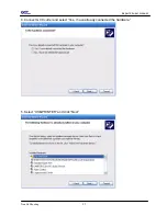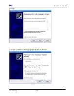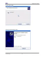
background image


  Expert 24 user manual


Trouble Shooting                                                                           

5-2

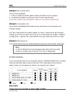
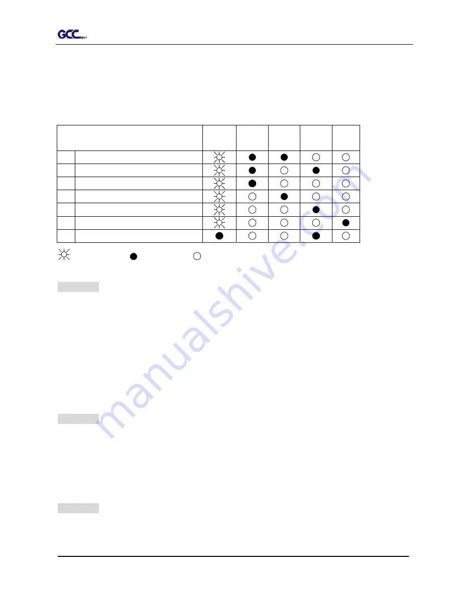
5.2.1 Warning Indicators 

 
When the ERROR LED flashes (as shown below), take the necessary actions according to 
the following instructions. When the problems are solved, the ERROR LED will turn off 
automatically. Pressing the ON/OFF LINE button can also turn off the ERROR LED. 
 

Warning Indicators 

ERROR

ON/OFF 

LINE 

REPEAT

DATA 

CLEAR 

CUT 

TEST 

Graph was clipped 


HPGL/2 command Error 


Lever up or no media 


4 Cannot 

repeat 


5 Communication 

error 


Width sensor error 


Check media, drum or X motor 


  = flash             

  = on               

 = off


Warning 1

 The graph is clipped     

This condition indicates that the cutting graph is bigger than the cutting area.   
 
You can solve the problem by:   
1.  Reload a wider or longer media.   
2.  Move the pinch rollers to widen the cutting area.   
3.  Re-scale the graph to a smaller size. Then send the cutting job again from your computer 

to the cutting plotter. 


Warning


HPGL/2 command error     

If the cutting plotter cannot recognize the commands from your computer, please check the 
commands applied to your cutting plotter in the HP-GL/2 or HPGL commands. Then send the 
same job to the cutting plotter again. 
 
If that doesn’t solve the problem, please contact your local dealer. 
 

Warning 3 

Lever up or no media       

Check that you have lowered the lever down and make sure that you load the media before 
cutting. 
 

Содержание Expert 24

Страница 1: ...EXPERT 24 CUTTING PLOTTER User Manual Great Computer Corporation...

Страница 2: ...information contained in this user manual at any time without prior notice un authorized modification copying distribution or display is prohibited All comments queries or suggestions concerning this...

Страница 3: ...older a blade tip can fly out During an operation do not touch any of the moving parts of this machine such as the carriage Also be careful to make sure that clothing and hair do not get caught Always...

Страница 4: ...Blade Installation 2 5 2 4 Media Loading 2 7 2 5 Cable Connections 2 9 3 Operation 3 1 The Control Panel 3 1 3 2 VLCD 3 2 3 3 File Uploader 3 5 3 4 Data Transmission 3 6 4 Basic Maintenance 4 1 Clean...

Страница 5: ...assistance Item Quantity Cutting Plotter 1 Set Accessories 1 Set 1 Installation CD 2 AC Power Cord 3 Desktop Support Brackets 4 Cutting Pad 5 USB Cable 6 RS 232 Cable 7 Tweezers 8 Paper Slicer 1 Gene...

Страница 6: ...ith clear guideline marks D Tool Carriage To help perform cutting job with installed blade or pen E Blade Holder To hold the blade F Platen The surface for holding and supporting media in operation G...

Страница 7: ...1 3 Object Description K AC Power Connector To insert the AC power cord L Fuse 3Amp M Power Switch To turn on or off the machine N USB Connector To connect the machine and a computer through a USB ca...

Страница 8: ...sily from any direction z Keep enough space for the machine accessories and supplies z Keep the working area stable avoiding severe vibration z Keep the temperature between 15 and 30 60 86o F in the w...

Страница 9: ...z 1 Left side vertical stand z 1 Right side vertical stand z 1 Support for left side z 1 Support for right side z 1 Stand Beam z 2 Bottom Stands with wheels z 2 Sliding brackets for paper take up z 1...

Страница 10: ...rews into the holes but do not tighten them at this step T stand Stand Beam Figure 2 2 Step 4 Position both the left Support and right Support perpendicularly to the T stand and put the screws into th...

Страница 11: ...and under the plotter and insert the screws into the holes on the bottom of the plotter but do not tighten them up as shown in Figure 2 4 Figure 2 4 Step 6 Tighten the screws of step 3 and step 5 Plac...

Страница 12: ...Step 2 Install blade Figure 2 7 Push the blade to the bottom of the blade holder Figure 2 8 Figure 2 8 Figure 2 7 Step 3 Adjust the blade tip to suitable length by screwing Blade tip adjustment screw...

Страница 13: ...e a new one 9 If the material cannot be cut through by higher cutting force you may need to replace a new one 9 If the blade is broken you have to replace a new one Caution The blade will lose its sha...

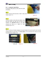
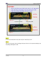
Страница 14: ...e 2 12 Step 2 Load your media on the platen and slide it under the pinch rollers from either the front side or the backside The alignment rulers on the platen extension will help you to adjust the med...

Страница 15: ...eft sides of media 9 Position the Secondary Pinch Roller at the center of media O Correct Figure 2 16 Figure 2 17 X Incorrect Primary Pinch Roller Secondary Pinch Roller Step 4 Push the lever backward...

Страница 16: ...ter through a USB Universal Serial Bus or a Serial O X 2 You can use the stand with flexible hardware setup and Chapter 2 4 1 for media loading 2 T port RS 232C This chapter shows you how to connect t...

Страница 17: ...9 in your system 9 If you are using Windows 2000 or XP as your operating system make sure you log in using the Administrator account If there s an USB driver of previous version installed please remo...

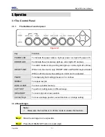
Страница 18: ...LINE and PAUSE keys activated While in off line mode the settings in VLCD can be adjusted PAUSE To temporarily halt cutting process or to continue REPEAT To repeat last job DATA CLEAR To clear up buf...

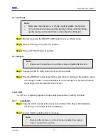
Страница 19: ...tion Step 1 Press the ON OFF LINE button to set as off line mode Step 2 Press the REPEAT button to perform re plot function starting at the position where the carriage locates It is also available to...

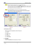
Страница 20: ...that you are going to use Step 4 Press the Connect button to connect your computer and the cutter If the connection succeeds the model info firmware version and adjustable parameter columns will be s...

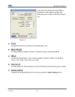
Страница 21: ...efault 50 Media Weight To choose different weights of media in two options Heavy and Light Default Offset To adjust the blade offset to ensure cutting quality in 8 options 0 000 0 175 Default 0 250 0...

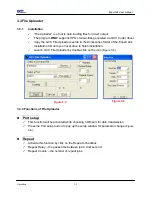
Страница 22: ...local drive to finish installation 9 Launch GCC File Uploader by double click on the icon Figure 3 5 Figure 3 5 Figure 3 6 3 3 2 Functions of File Uploader Port setup 9 This function will be activated...

Страница 23: ...generated by SignPal can be transmitted directly to the plotter at the DOS prompt and then be cut out Before outputting at the DOS prompt set up a transmission protocol between your cutting plotter an...

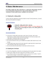
Страница 24: ...int free cloth If necessary clean it with a water rinsed or an alcohol rinsed cloth Wipe the cutting plotter to remove any residues on the cutting plotter Finally absorb water with a soft lint free cl...

Страница 25: ...ing use a lint free cloth or cotton swab to wipe away the accumulated dust from the rubber portion of the pinch rollers To prevent the pinch rollers from rotating while cleaning use your fingers to ho...

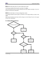
Страница 26: ...heck the following items first Is the power cord plugged in properly Is the power cord connected to the power connector properly Is the power switch turned on properly Why doesn t the cutting plotter...

Страница 27: ...aph is clipped This condition indicates that the cutting graph is bigger than the cutting area You can solve the problem by 1 Reload a wider or longer media 2 Move the pinch rollers to widen the cutti...

Страница 28: ...8 bits 1 stop bit Then press ON OFF Line key to switch back to On Line mode Warning 6 Width sensor error Check that the pinch rollers are positioned above the grid drum and reload the media again In o...

Страница 29: ...e an obstruction to the carriage relating to a problem on the Y axis Please clear the obstruction and check that the carriage can move smoothly Then turn on the power and reboot the cutting plotter 5...

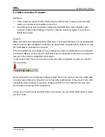
Страница 30: ...d the USB cable is connected to computer When the USB driver was installed on one USB port and then the USB cable is re connected to another USB port on the same PC next time most of computers will sh...

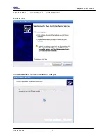
Страница 31: ...Expert 24 user manual Trouble Shooting 5 6 1 Select Start Control Panel Add Hardware 2 Click Next 3 It will take a few minutes to detect the USB port...

Страница 32: ...Expert 24 user manual Trouble Shooting 5 7 4 Connect GCC cutter and select Yes I have already connected the hardware 5 Select USB PRINTER and click Next...

Страница 33: ...Expert 24 user manual Trouble Shooting 5 8 6 Finish 7 Choose Install the software automatically Recommended...

Страница 34: ...Expert 24 user manual Trouble Shooting 5 9 8 Wait a few minutes 9 Now you can drive GCC cutter...

Страница 35: ...e 250g Max Cutting Speed Diagonal 400 mm sec 15 7 sec Software Resolution 0 025 mm Repeatability 0 1mm Re plot Memory 500 Kbyte Interfaces USB RS 232 Commands HP GL HP GL 2 Configurable Origin Yes Con...

Отзывы: